Elli Charger 29
EN
Set DIP-switches
6. Set DIP-switches
The power board has two groups of 5-pin DIP-switches:
— Group A determines the coil type used for the current transformer and defines
the ground loss monitor functionality.
— Group B determines the maximum available current of the facility/house,
or of the wallbox itself, depending on the group A configuration.
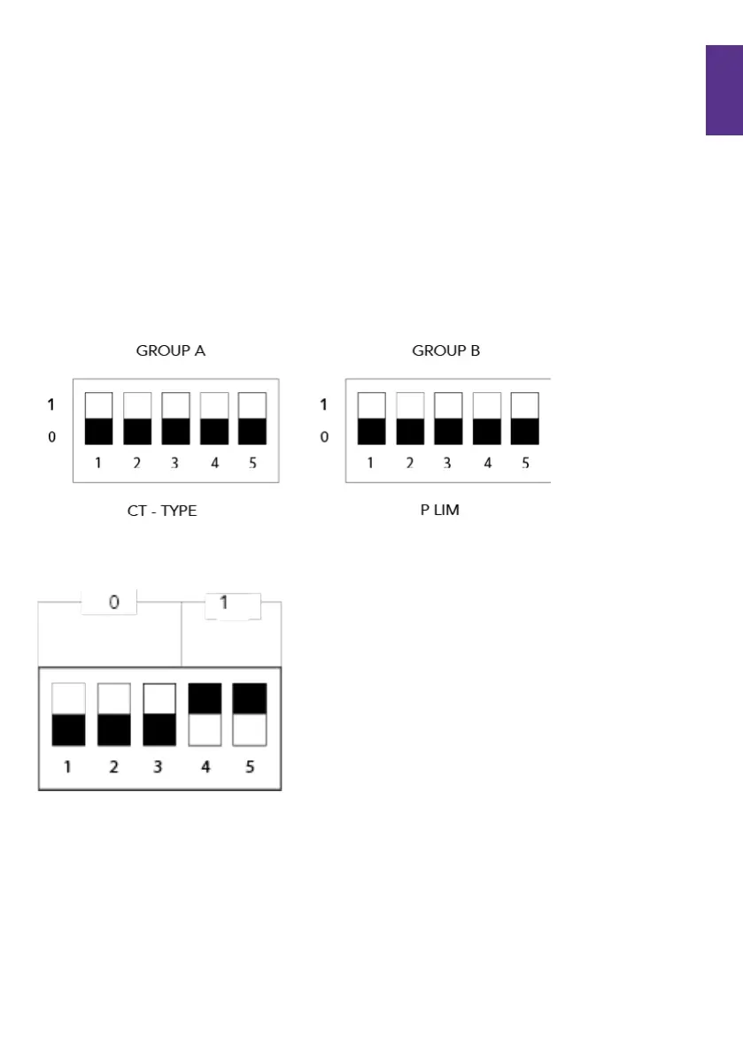
In the following illustrations and tables, the upper switch position is being referred to
as position 1, whereas the lower switch position is being referred to as position 0.
DIP-switch positions:
Example of DIP-switch setting: 0, 0, 0, 1, 1
 Loading...