20
Control System
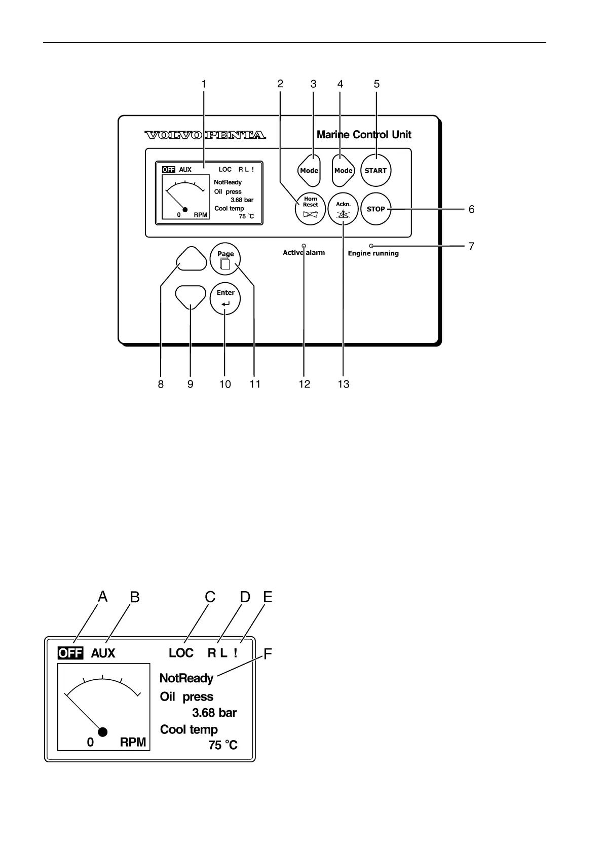
1. LCD display
2. Horn reset (stops sound alarm)
3. Mode Left, toggles modes backwards
[Off - AUX(EME,HRB,PRP)]
4. Mode Right, toggles modes forwards
[Off - AUX(EME,HRB,PRP)]
5. Start button
6. Stop button
7. LED - Engine running
8. Up button (Select and Increase)
9. Down button (Select and Decrease)
10. Enter (confirmation of selection)
11. Page, toggles screens
(Measurement - Adjustment - History)
12. LED - Active alarm
13. Acknowledge button
A. Highlighted indicates OFF-mode
B. Highlighted indicates operational mode
AUX (EME, HRB or PRP)
C. Indicates Local mode
D. R - Remote connection
(Slave Panel or PC Software)
L - Access lock
E. ! - Active alarm
F. Engine state (NotReady - Ready - Running)
MCU Panel layout
Display
 Loading...