250
Transmission Modes WAVECOM Decoder W74PC, W-PCI/e, W-CODE, W-CLOUD Manual V9.1.0
The KG-84 bit stream contains a 64 bits long header followed by two 256 bit message blocks in turn fol-
lowed by encrypted data terminated by an End-Of-Message. Hence synchronization can only be achieved
at the start of transmission using the KG-84 header.
The length of a message is variable. Messages are usually sent consecutively with a short idle sequence
between each message.
STANAG-4481-PSK
This STANAG mode is specified by the NATO (North Atlantic Treaty Organization) Military Agency for
Standardization as a "Minimum technical equipment standards for naval HF shore-to-ship broadcast sys-
tem".
The modulation technique used in this mode is based on the operating conditions encountered by naval
broadcasts.
The technology utilizes binary phase shift keying (BPSK) of a single tone 1800 Hz sub-carrier with a con-
stant modulation speed of 2400 Bd. Through the use of BPSK modulation and a FEC coding rate of 1/4,
the effective user data rate is 300 bps.
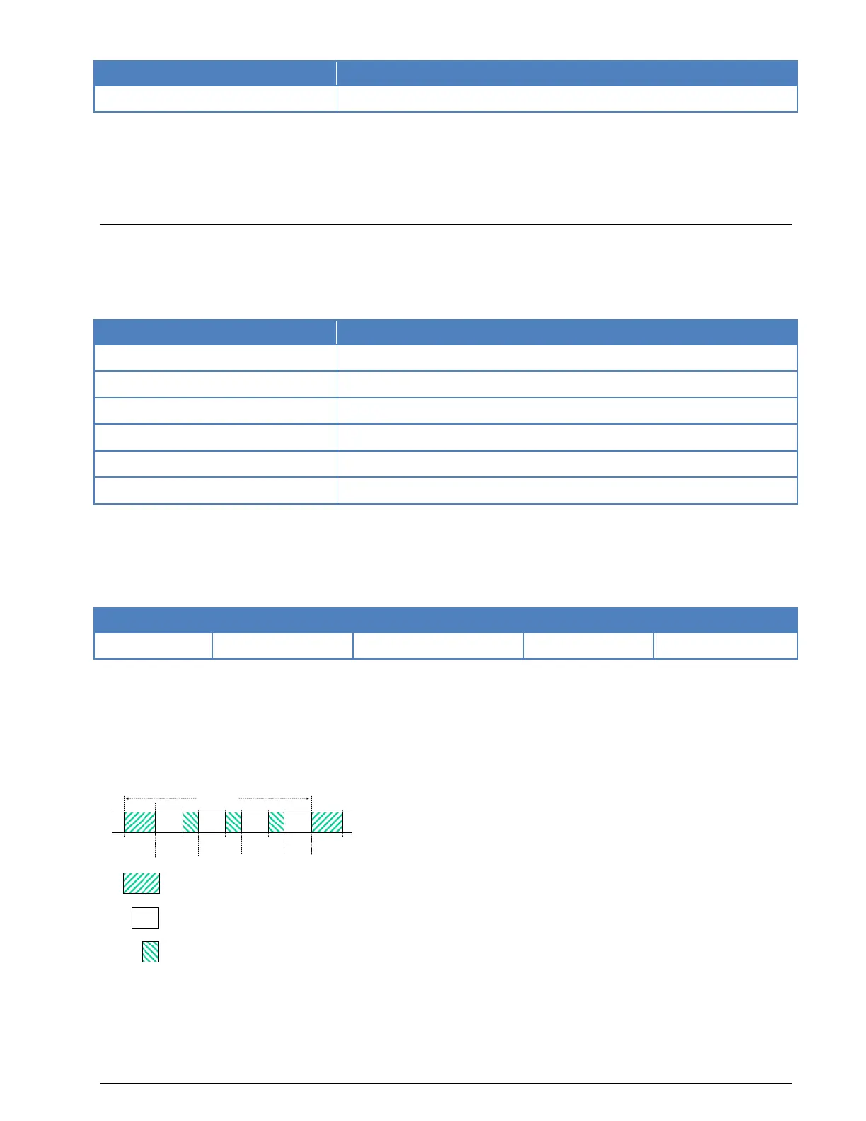
The user data is transmitted using a continuous frame structure with 213.33 ms per frame. Each frame
starts with a preamble containing 80 symbols. The following 176 symbols are divided into four 32-symbol
data segments and three 16-symbol channel probe segments.
The 176-symbol data-probe segment immediately follows the next frame, beginning with the same 80-
symbol preamble. This repeated frame structure enables synchronization of the demodulator at any time
of transmission.
At the end of transmission, an EOM bit pattern (0x4B65A5B2, MSB first) is sent to mark the end of mes-
sage. The EOM sequence is followed by flush bits, to flush the FEC coder and to complete the transmission
of the remainder of the interleaver data block.
16 16 1632
32
32 32
80 80
Block 1 Block 2 Block 3 Block 4
T = 213.33 ms
80
16
32
Preamble symbols
Data symbols
Channel probe symbols
Preamble
 Loading...