Installation and electrical connection | 6
5111967A OI-II Webasto Unite 13 / 37
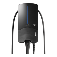
6.7 Setting the DIP switches
Fig.19
1
Reserved
2
Enable Potential free contact/Load shedding
3
Locked Cable Function (only for socket models)
4, 5, 6
Power Optimizer (requires optional accessories)
NOTE
DIP-switch settings
DIP-switch settings are optional. All settings can be
changed by using the Setup App, or the web configura-
tion interface (see chapter8, "Unite Configuration Inter-
face" on page 20).
u
The most recent made setting will always be ap-
plied.
u
The current setting is shown in the web configura-
tion interface.
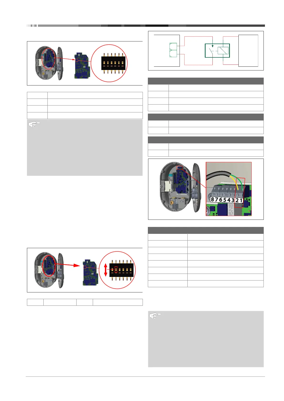
6.7.1 Enable Potential free contact/Load
shedding
Your charging station can be controlled with external potential-
free contacts (on/off function) for integration of the charging
station into:
l car park automation systems
l energy supplier ripple control devices
l timer switches
l photovoltaic inverters
l auxiliary load control switches
l external key lock switches
l etc.
Fig.20
ON
Enabled
OFF
Disabled
1. Set DIP switch 2 in the ON position to enable the external
enable function, or in the OFF position to disable the ex-
ternal enable function.
1
CN2
EVSE
RL
1
4
2
3
2
Carpark
Automation
System
Control
Fig.21
Pos. Description
CN2
Connector 2
RL
Relay
A
Main board charging station
B
Car Automation System Control
Pin assignments connector 2
1 Pin 1
2 Pin 2
Pin assignments Relay
1, 2 Potential free contacts
3, 4 Relay coil
Fig.22
Terminal Function
1 (CN2-1) Potential free contact /Load shedding
2 (CN2-2) Potential free contact/Load shedding
3 (CN2-3) Load Shedding Input +
4 (CN2-4) Load Shedding Input -
5 (CN2-5 Power optimizer meter B (COM)
6 (CN2-6) Power optimizer meter A (COM)
7 (CN2-7) -
8 (CN2-8) -
1. Mount the wiring according to the illustration and table
above.
– Charging is disabled when the external relay contacts
are in the open position.
NOTE
DIP-switch settings
DIP-switch settings are optional. All settings can be
changed by using the Setup App, or the web configura-
tion interface (see chapter8, "Unite Configuration Inter-
face" on page 20).
u
The most recent made setting will always be ap-
plied.
u
The current setting is shown in the web configura-
tion interface.

 Loading...