6 | Installation and electrical connection
16 / 37 5111967A OI-II Webasto Unite
Fig.36
The power optimizer meter must be installed just after the
mains switch of the house, as shown in the illustration above.
1. Install the power optimizer meter
2. Install the wiring according to the figure and table below.
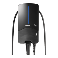
Fig.37
Terminal Description
5 (CN20-1) B (COM)
6 (CN20-2) A (COM)
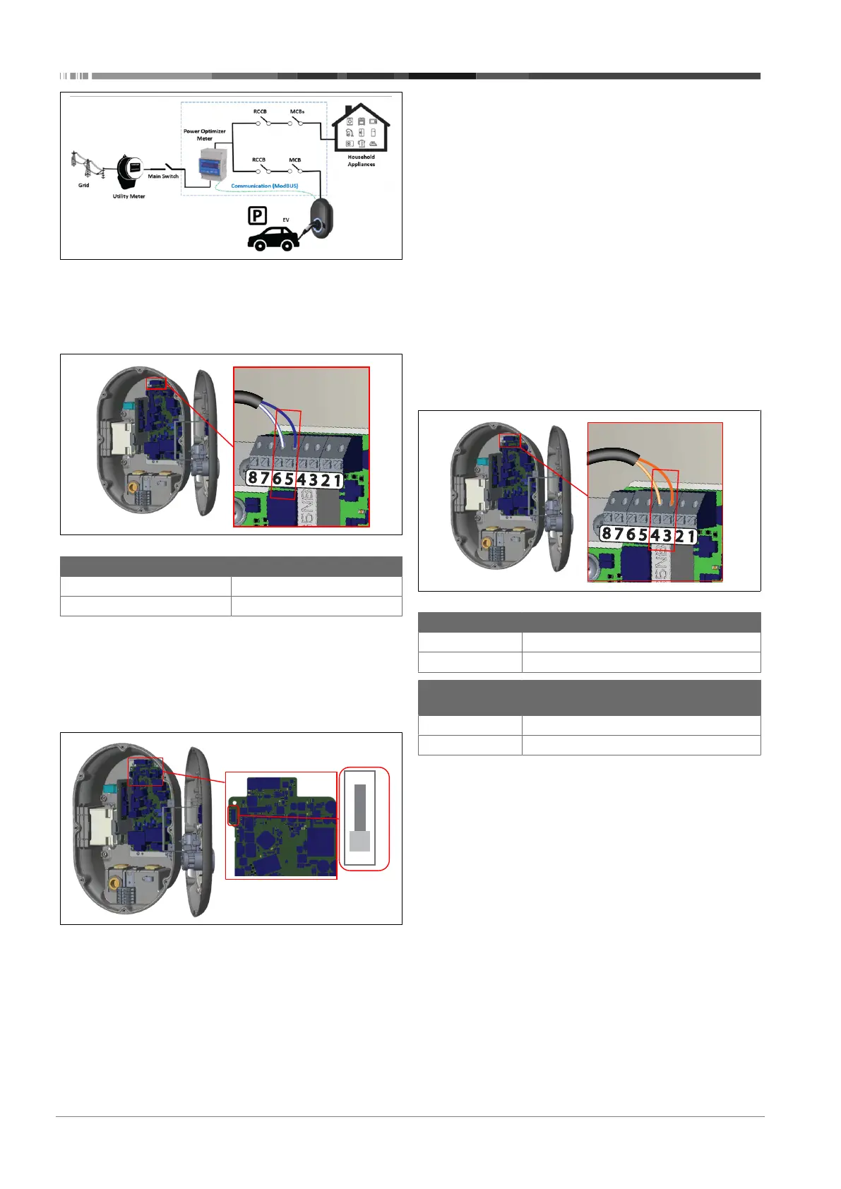
6.8 Using the Mode selection switch
The Webasto Unite has the following modes:
l Operation Mode 1 (Standard Charging): This mode is the
factory default setting.
l Operation Mode 2 No function
l Operation Mode 3 No function
Fig.38
l The mode selection switch must be in position 1.
6.9 Setting up Load shedding /
Potential-free contact
The Webasto Unite supports load shedding. Load shedding
provides immediate charging-current reduction in case of lim-
ited supply. Load shedding can be used in any mode, including
Standalone and OCPP-connected modes. The load-shedding
triggering signal is a dry contact, (potential free) signal. This sig-
nal must be provided externally, and must be connected to ter-
minals 3 and 4 on the power board.
l When load shedding is activated by closing the contacts
with an external device (such as ripple control receivers),
then the charging current is reduced to 8 A.
l When load shedding is deactivated by opening the con-
tacts, then the charging process continues at the maximum
available current.
l In a normal state, when there is no signal connected to the
load shedding input (contacts open between terminal 3
and 4), the charging station supplies the maximum avail-
able current.
Fig.39
Terminal Input
3 Load Shedding Input +
4 Load Shedding Input -
Load Shedding
Input State
Behaviour
Open Contact Charge with maximum available current.
Closed Contact Charge with 8 A.
l Connect the potential free contact load-shedding signal.

 Loading...