COMBUSTION CHAMBER
INSTALLATION & SERVICING INSTRUCTIONS FOR WORCESTER GREENSTAR HEATSLAVE EXTERNAL 12/18-18/25-25/32
8 716 113 389d (03/2010)
23
INSTALLATION
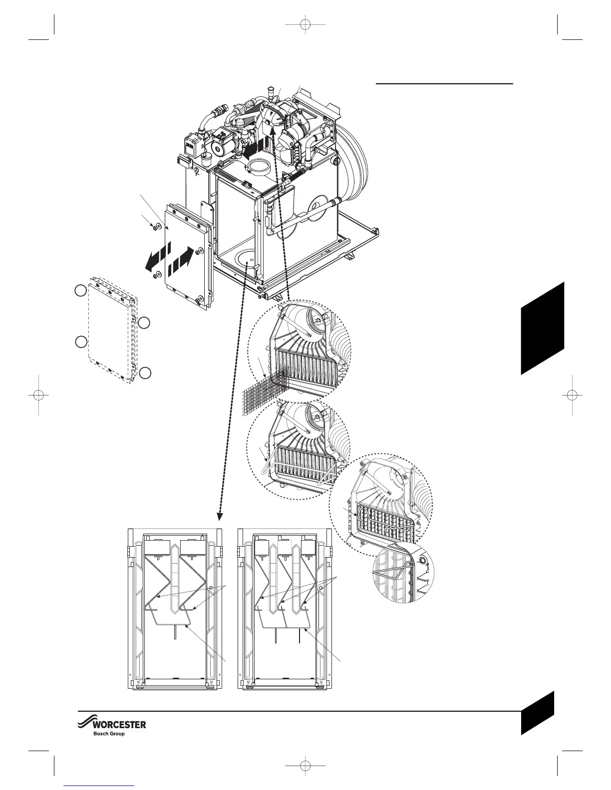
Combustion chamber:
1 Release retaining nuts and washers (B).
Remove combustion chamber access
door (A).
2 Ensure the baffles (C) and baffle retainer
(D) are correctly fitted for the boiler output
as shown in the plan views opposite.
3 Refit combustion chamber door (A).
IMPORTANT: Secure with nuts and
washers (B) and tighten, using the
sequence shown in figure 3a, until the
chamber door is firmly secured, do not
over tighten the nuts.
4 Unscrew screws (E) and remove flue
manifold access cover (F).
5 Check that all the baffles (G) and baffle
retainer (H) or ( J ) are correctly fitted to the
secondary heat exchanger.
COMBUSTION CHAMBER
 Loading...