EasyManuals Logo
Home>Worcester>Boiler>12/18

Worcester 12/18 User Manual

Worcester 12/18
56 pages
To Next Page IconTo Next Page
To Previous Page IconTo Previous Page
Page #52 background imageLoading...
Page #52 background image
Boiler not
operating
with a
heating /
hot water
demand
Burner
motor runs?
Lockout
within 1
second?
Replace
control box
Replace
motor/pump
Check boiler
controls &
supply
Replace
motor
L & Nto
control box?
Motor or
pump
seized?
Photo cell
functional?
Solenoid coil
functional
(100)?
Replace
photo cell
Motor gives
50 Volts on
white wire?
Lockout
after 12 sec
purge?
Replace
control box
Replace
solenoid coil
Replace
motor
Ignition
spark
proved?
Oil to pump?
Drive
coupling
broken?
Purge
pressure
1-2 bar?
Pump
produces
pressure?
Replace
pump stem
valve,
pressure
OK?
Replace
solenoid coil
Pipe to
nozzle
holder OK?
Replace
nozzle
Replace oil
pump
Replace
control box
Eectrodes &
leads OK?
Yes
No
NO
Yes
No
Yes
No
Yes
Yes
No
No
Yes
Yes
No
No
Yes
Yes
No
Yes
Motor 40
between blue &
black wires ?
Replace
control box
Yes
Yes
No
Yes
No
Yes
No
No
No
Yes
No
Nozzle
atomising
fuel?
Combustion
air setting
correct?
Yes
Yes
Combustion
head set
correctly?
Solenoid operating?
Increase the pump
pressure, pressure OK?
Solenoid coil
functional
(100)?
No
Coil lead
OK?
Yes
Yes
Replace
control box
No
If BF, remove
burner
snorkel tube
& retest
.
Burner OK?
Flame off &
re-lights?
Yes
Photo cell
functional?
No
Yes
Replace
photo cell
No
Boiler or flue
blocked
No
Reseal BF
or reposition
terminal
Yes
Replace
control box
Yes
Replace
electrodes/
leads
No
Unblock or
replace pipe
No
Reset air
setting
No
Reset
combustion
head
No
Yes
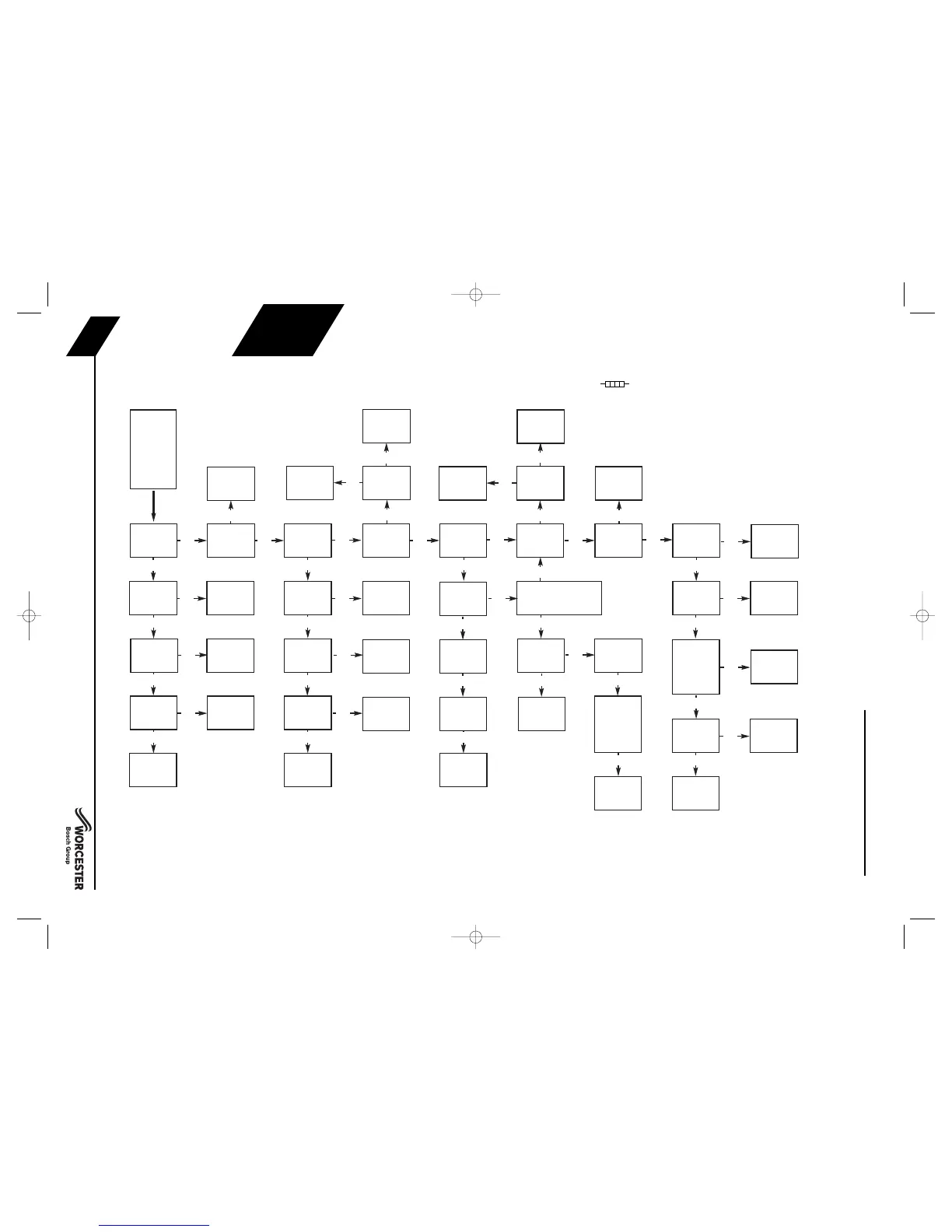
FAULT FINDING LOGIC FOR
RIELLO CONTROL BOXES
All resistance measurements are actual measured values and some variation is to be expected, therefore measured
values should be similar to but not necessarily identical to the given values.
The operation of the photo cell can be tested by measuring the resistance across the photo cell, it should be a high
resistance (greater than 10M or open circuit) in the dark and low resistance (3k or less) in light.
Burners on balanced flue systems can recirculate flue products resulting in the burner cycling, if this happens check the
flue system integrity and the terminal position.
These fault finding charts are provided to assist competent and suitably qualified engineers
to locate and rectify faults. Whilst every effort has been taken to ensure the information
given is correct and complete we cannot guarantee that every eventuality has been
covered.
Worcester, Bosch Group cannot be held responsible for costs incurred by persons not
deemed to be competent.
MO535 IMPORTANT NOTE: The box has a built in delay of 11 seconds before activating the motor.
The preheater link must be fitted at
A
for the box to operate
FAULT FINDING
& DIAGRAMS
FAULT FINDING
INSTALLATION & SERVICING INSTRUCTIONS FOR WORCESTER GREENSTAR HEATSLAVE EXTERNAL 12/18-18/25-25/32
8 716 113 389d (03/2010)
52
8 716 113 389d 30/3/10 14:01 Page 52

Questions and Answers:

Question and Answer IconNeed help?

Do you have a question about the Worcester 12/18 and is the answer not in the manual?

Worcester 12/18 Specifications

General IconGeneral
BrandWorcester
Model12/18
CategoryBoiler
LanguageEnglish

Related product manuals