July 2019
4-3
Xerox® B205/B215 Multifunction Printer Service Manual
REP 1.1
Repairs / Adjustments
Initial Release
REP 1.1 Main PWB
Parts List on PL 1.1
Removal
WARNING
Do not perform repair activities with the power on or electrical power supplied to the
machine. Some machine components contain dangerous electrical voltages that can
result in electrical shock and possible serious injury.
DANGER: Ne pas effectuer de dépannnage avec le contact principal activé ou avec l'ali-
mentation électrique appliquée à la machine. Certains éléments de la machine compor-
tent des tensions électriques dangereuses qui peuvent causer un choc électrique et de
g
raves blessures.
AVVERTENZA: Non effettuare alcuna riparazione con l'alimentazione elettrica inserita.
Al
cuni componenti contengono corrente ad alta tensione che può provocare forti
scosse e gravi ferite.
VORSICHT: Es dürfen erst Reparaturarbeiten durchgeführt werden, wenn das Gerät aus-
geschaltet ist oder der Netzstecker nicht mehr mit der Stromquelle verbunden ist. Einige
K
omponenten des Gerätes sind stromführend und können daher zu ernsthaften Verlet-
zungen oder Stromschlägen führen.
AVISO: No realice reparaciones con la máquina encendida o conectada a la corriente.
Al
gunos componentes de la máquina contienen voltajes eléctricos peligrosos que
pueden producir una descarga eléctrica y causar daños graves.
1. Record the machine serial number from the Data Plate (located on the rear cover beneat
h
t
he bar code) or from a Configuration Report printed prior to installing the new PWB.
Refer to, GP 2, Machine Reports.
2. Switch off the machine, then disconnect the power cord.
3. Remove the Right Side Cover, RE
P 2.2.
4. Remove the Wifi PWB, REP 2.7.
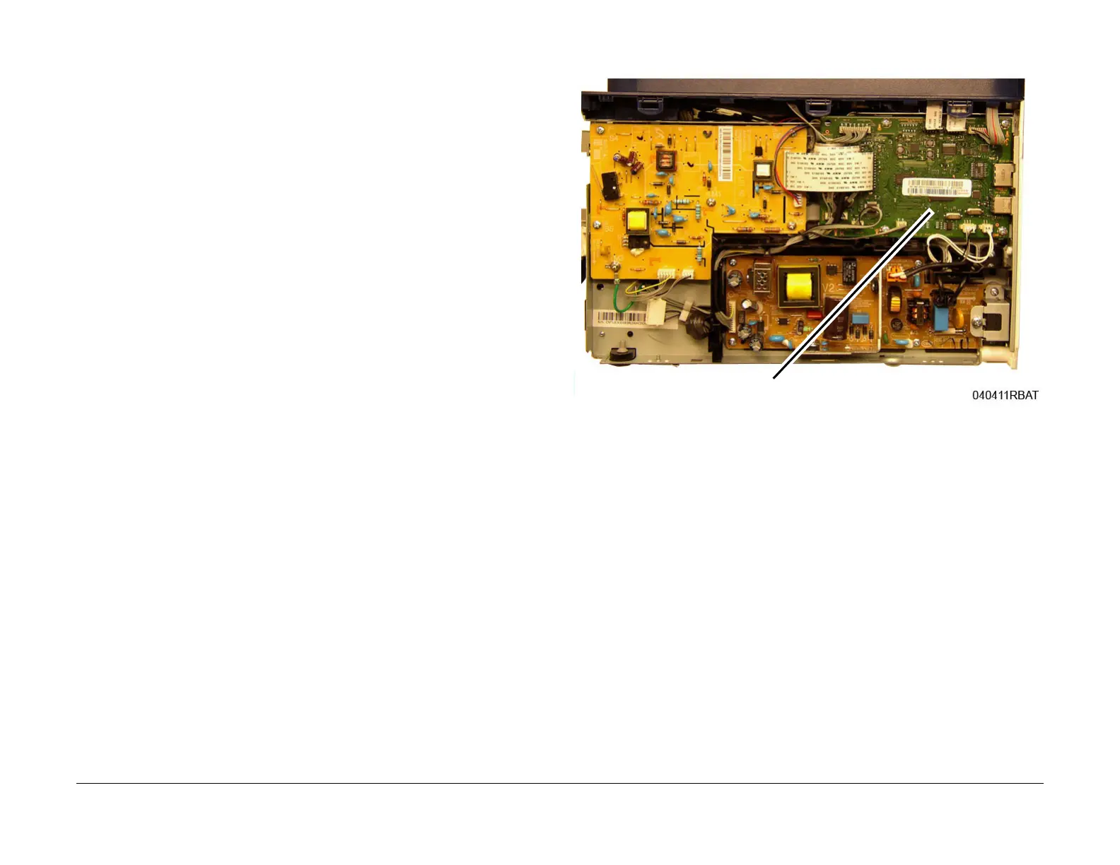
5. Remove the Main PWB, Figure 1.
a. Disconnect all the connectors on the Main PWB.
b. Remove the screws (5) and the Main PWB.
Figure 1 Main PWB removal
Replacement
NOTE: Tapered plastic screws and round machine screws are used to hold the PWB to the
frame. Make sure that the plastic screws go into plastic components and machine screws go
into the metal frame.
The replacement is the reverse of the removal procedure.
After installing a new Main PWB, the following steps MU
ST be performed to write the machine
serial number to the new Main PWB:
1. Reconnect the power cord, the switch on the machine.
2. Set the serial number to the original machine number recorded in Step 1 of the Remova
l
proce
dure.
• B215
a. Enter Diagnostics, GP
1. Open [Data Setup, Machine Data, Set Serial Num-
ber],
then enter the original serial number from Step 1. Touch [OK].
• B205
a. Enter Diagnostics GP
1. Using the up and down arrows, enter: [Data Setup,
Machine Data, Set Serial Number], then enter the original serial number from
Step 1. Press the [OK] button.
3. Perform <
Clear All Memory> in Diagnostics: [Data Setup, Machine Data, Clear All
Memory].
 Loading...