(MCCB)
(mm)
(mm)
(mm)
10
16
16
25
32
40
63
63
100
100
125
160
200
200
250
250
350
400
500
600
600
16
25
32
40
40
63
63
100
100
125
125
160
160
350
400
400
600
600
2.5 2.5
44
44
6
6
10 10
10 10
16 16
16 16
25 25
25 25
35 35
35 35
50 35
70 50
120 120
150 150
185 185
150*2
150*2
150*2
150*2
2.5 2.5
10
10
10
2.5 2.5
1.5
1.5
15
2
2
2
()A
()A
EH640A2.2G/3.7P
EH640A1.5G/2.2P
EH640A0.7G/1.5P
EH640A3.7G/5.5P
EH640A5.5G/7.5P
EH640A7.5G/11P EH623A3.7G
EH640A11G/15P EH623A5.5G
EH640A15G/18.5P EH623A7.5G
EH640A18.5G/22P
EH640A22G/30P EH623A11G
EH640A30G/37P EH623A15G
EH640A37G/45P EH623A18.5G
EH640A45G/55P EH623A22G
EH640A55G/75P EH623A30G
EH640A75G/90P EH623A37G
EH640A90G/110P
EH640A110G/132P
EH640A132G/160P
EH640A160G/185P
EH640A185G/200P
EH640A200G/220P
EH640A220G/250P
800
600
185*2
185*2
EH640A250G/280P
EH640A280G/315P
16
16
20
32
20
42.5
64
2.5 2.5
10
10
16
2.5 2.5
1
1.5
1.5
1.5
EH620A1.5G EH623A1.5G
EH620A0.7G EH623A0.7G
EH620A0.4G
EH620A2.2G EH623A2.2G
.5
1.5
1.5
1
1.5
1.5
1.5
.5
1.5
1.5
1
1.5
1.5
1.5
.5
1.5
1.5
1
1.5
1.5
1.5
.5
1.5
1.5
600
600
150*2
150*2
1.5
800
800
150*3 150*3
EH640A315G/350P
EH640A350G/400P
1.5
800
800
185*2
185*2
1.5
800
800
150*4
150*4
1.5
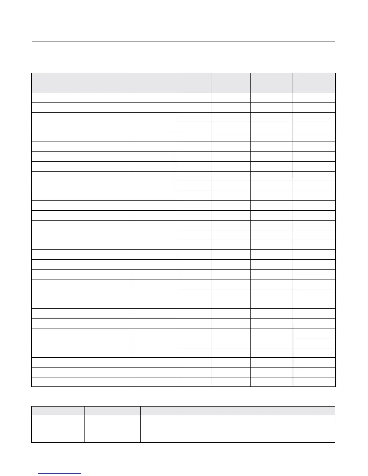
Chapter 3 Mechanical and Electrical Installation
3.2 Electrical Installation
1、Guide to the external electrical parts :
2、Use instruction to the external electrical parts :
Curcuit breaker Front end of input loop
Connected between the
circuit breaker an the
inverter input side
Switch off the power supply when the equipment at the lower part is over current .
Switch off the inverter , avoid switching on/off the inverter frequently by using the
contactor directly (less than twice in a minute)
Contactor
Circuit breaker
Inverter model
Contact
Input cables Output cables Control cables
Part Mounting location Function description
 Loading...