55
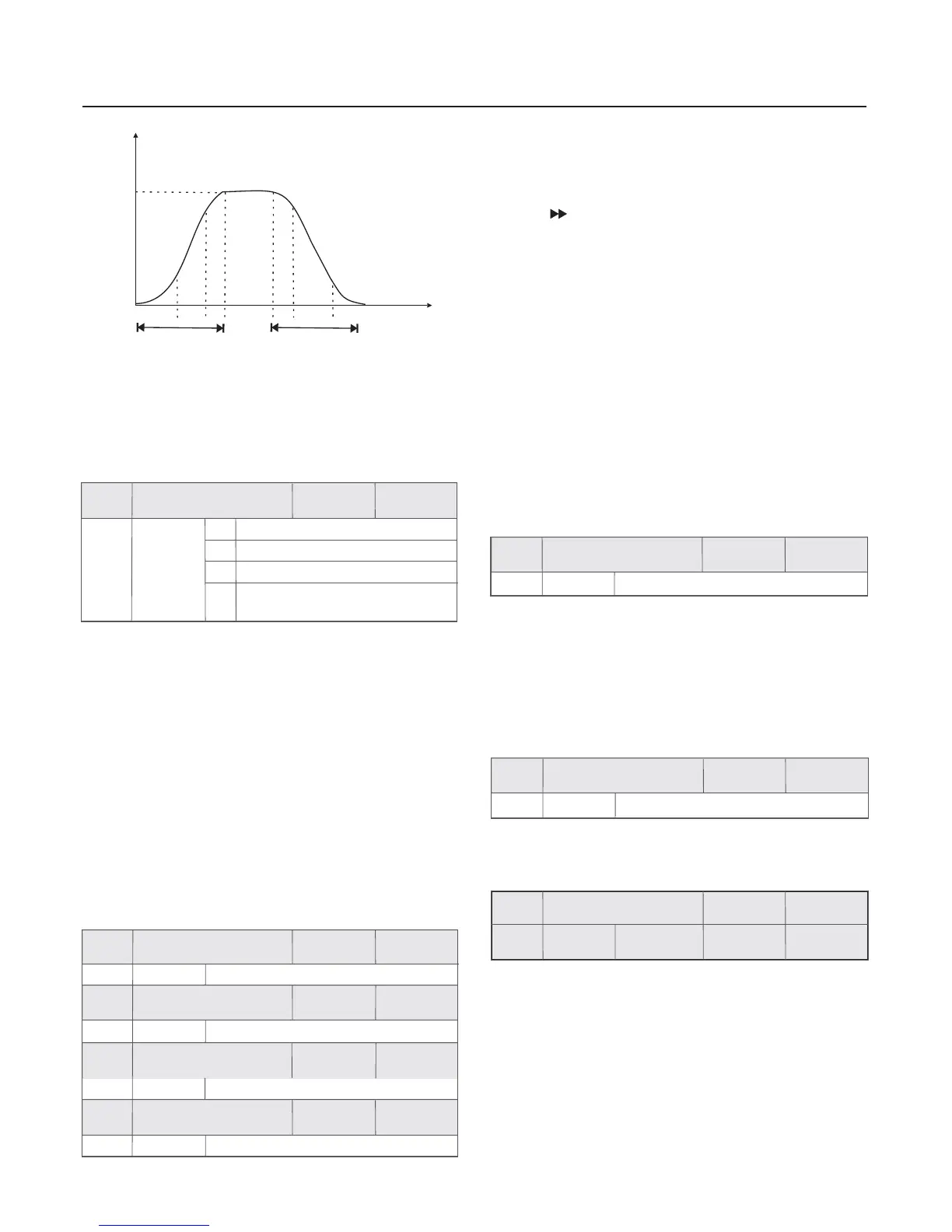
Fig.6-13 Schematic Diagram for S curve
Acceleration/Deceleration
0 S Key function disabled
1
2
3
0 8191~
1 8191~
0 8191~
1 8191~
0 This key has no function .:
2 Reverse rotation run command
The S key of operation panel used as reverse
rotation run command , when the keyboard control mode
(F0.02) is 0 , press the key, then the inverter will output
frequency from the phase order.
:
input of the
reverse
1 Forward rotation Jog command
It can realize forward rotation Jog (FJOG) through the S
key on the keyboard .
:
Group F6 Keyboard and Display
S Key refers to multifunctional key .T
can be set and defined by the parameter .
he function of S key
3 When the exact stop mode is enabled (FA.11 0), press S
key, then will be clean out.
:≠
the data of the exact stop process
Please refers to the description of FA.11 for exact
stop mode.
detailed
t1 t1
t2 t2
Fmax
Frequency
Time
acceleration time
deceleration time
The corresponding relationship between the binary bite of
F6.01 F6.02 running display parameter and FV parameter
number is shown as attached fig.3 .
、
There are two examples about the setup way of F6.01 to F6.04
in the following.
1:
Client wants to display FV.00 , FV.02 and FV.18 circularly
in the running state .
Setting as following : F6
.
01=1+4=5 F6
.
02=32
2:
Client wants to display the setup frequency (FV.01) in the
stop state
Setting as following :
F6. 03 =
2
F6.01
F6.02
F6.03
F6.04
5
0
1
0
F6.00
S Key function
selection
1
Chapter 6 Parameter Description
Factory
default value
Factory
default value
Factory
default value
Factory
default value
Factory
default value
Setup range
Setup range
Setup range
Setup range
Setup range
Forward rotation Jog command
Reverse rotation run command
Clear the data of exact stop
process
LED running display
parameter 1
LED running display
parameter 2
LED stop display
parameter 1
LED stop display
parameter 2
In stop or running status ,when the status parameter(FV) needs
to be inquired again and again, by setting running parameter
(F6.01 to F6.02) and stop parameter (F6.03 to F6.04) , and
realizing the status parameter by controlling the
shift key( ) to display in turns .
The parameter value of F6.01 to F6.04 is set according to
binary system , by transforming it into decimal system .
When there needs to display one parameter of you
only need to set the corresponding binary bite of F6.01 to F6.04
as 1 .
common-using
input
FV,
The parameter is used to set FV parameter number of underside
range LED display of the double range LED operation panel,
please refer to FV parameter of page 35 .
It is convenience
the client to debug and monitor inverter running. As for
using exact stop function can realize setup value and
actual value at the same time through
.
for the details
the content of underside range LED display that
users who
displaying
displaying the double range
LED
1
1
Factory
default value
Factory
default value
0.0 100.0~
Auxiliary supervise
item selection
Load speed display
coefficient
5
02~
Setup range
Setup range
F6.06
F6.05
Please remember the user password correctly . If the password
is set wrongly or forgotten ,please contact the manufacturer .
Please refer to the description of password setting in 4.5 section .
The output frequency of the inverter and the load speed are
corresponding together through this parameter . It is set when
the load speed needs to be displayed .
0 Clear the previous user password and make the
password protection function invalid.
: setup
Once any non-zero number be set , the password protection
function will be enabled .
To view F6.08
you can only view
and modify this parameter when
under the status of password protection , the LED
will prompt user that the parameter is hidden ,
the password input correctly.
0
-
Factory
default value
Factory
default value
0 9999~
Reserved function
User
password
F6.07
F6.08
 Loading...