66
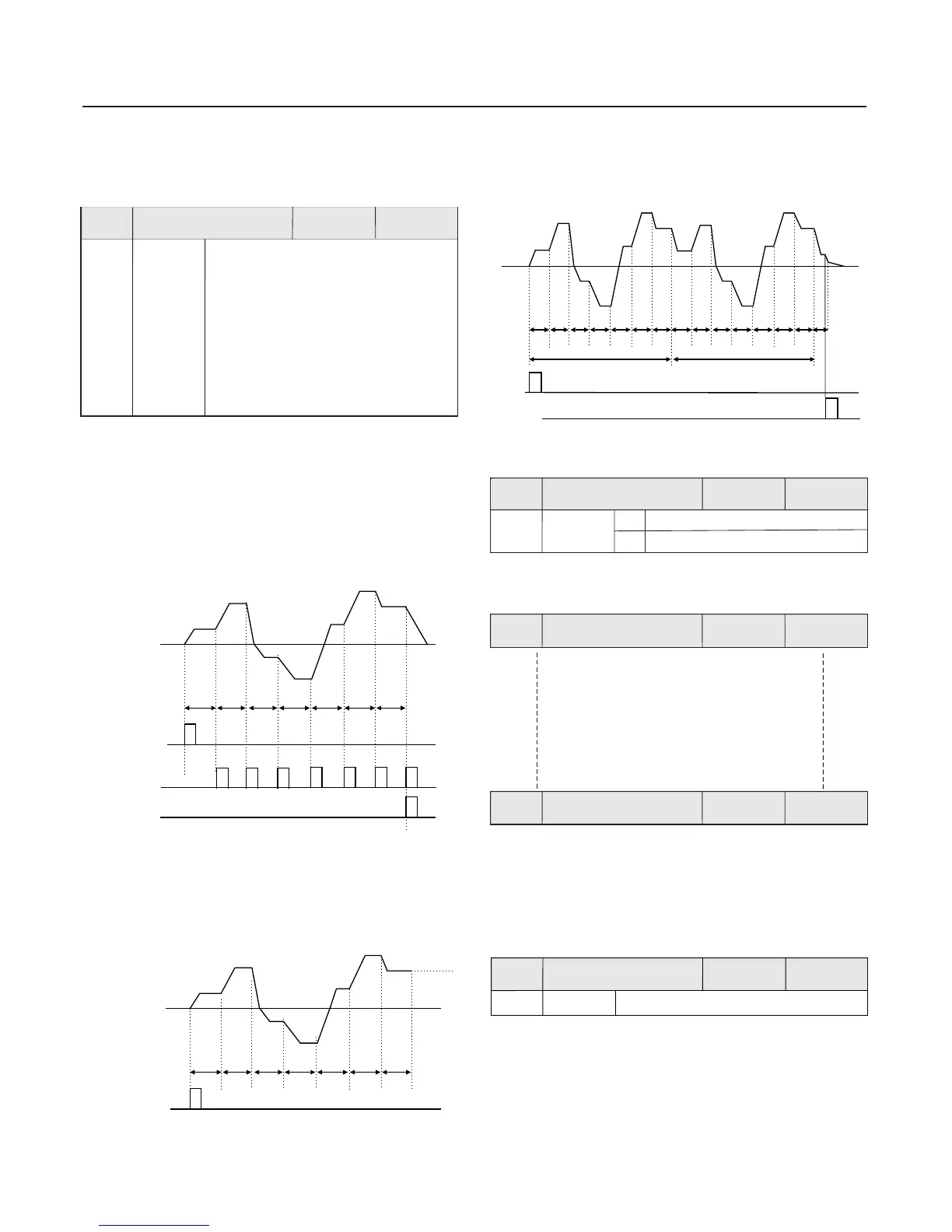
The inverter will automatically stop upon completing one
single cycle , and will not restart until another running
command is given .
The inverter will automatically keep the running frequency and
direction of last one segment upon completing one single cycle .
When the frequency source selections F0.07 , F0.03 and F0.04
are determined as PLC running mode ,
set to determine its
characteristics .
FB.00 to FB.15,FB.16,
FB.17 and FB.18 to FB.41should be
0 Stop upon completion of one-time running:
1 Keep final value upon the completion of one-time running:
Fig. 6-24 Stop Upon the Completion of one-time Running
Fig. 6-25 Keep Final Value Upon the Completion
of one-time Running
It is used to define every segment running time unit of
the sixteen segments program .
T1
T1
T2
T2
T3
T3
T4
T4
T5
T5
T6
T6
T7
T7
a1
a1
f1
f1
a2
a2
f2
f2
d3
d3
a3
a3
f3
f3
a4
a4
f4
f4
d5
d5
a5
a5
f5
f5
a6
a6
f6
f6
d7
d7
f7
f7
d7
RUN command
RUN command
Setup range
FB.16
PLC running mode
Factory
default value
00
Chapter 6 Parameter Description
The second part of LED PLC
running time unit selection
:
The second part of LED PLC running time unit selection:
0 second: 1 hour:
The first part of LED PLC action
mode
:
The first part of LED: PLC action mode
0 Stop upon the completion of
one-time running
:
1 Keep final value upon
the completion of one-time running
:
2 Constant circulation:
PLC
circulation
completion
PLC phase
completion
The inverter will automatically start next one cycle upon
the completion of one cycle , and will not stop until stop
command is given .
d1
d2
T1
d1
T7
f7
f1
Second time cycle
Fig. 6-26 Constant circulation
T6
f6
T5
f5
T4
f4
T3
f3
T2
f2
T1
f1
T7
f7
First time cycle
2 Constant circulation:
T6
f6
T5
f5
T4
f4
T3
f3
T2
f2
T1
f1
RUN
command
STOP
command
PLC power failure with memory means the memory of running
phase and frequency of PLC before power failure.
power failure without memory
0.0s
0000
power failure with memory
0
Factory
default value
Factory
default value
Factory
default value
As for the above parameters, refer to
the description of parameter table .
Phase 0 running time
Phase 14 /15 running
mode
PLC power-failure
memory selection
0
1
Setup range
FB.18
FB.17
FB.41
When several inverters drive the same load ,
the unbalanced load distribution, thereby, inverter with
higher speed has to carry heavier load . The droop control
characteristics can the speed droop with the addition of
load to balance the load distribution . The parameter is used to
adjust the frequency change value of the inverter with droop
velocity .
different velocity
leads to
change
Group Communication ParameterFC
0.0Hz
Group FD Particular Function
0.00Hz 10.00Hz~
For details, please refer to chapter 7.
FD.00
Factory
default value
Setup range
Droop control
 Loading...