FV.23
AO2 output
FV.24
Radiator temperature
FV.
25
Total running time
FV.00
Output frequency
FV.01
Setup frequency
(flashes)
(Flashes)
FV.02
Output current
FV.03
Running rev
FV.04
Setup rev (flashes)
FV.05
Running load speed
FV.06
Setup load speed
(flashes)
FV.07
Output voltage
FV.08
Bus voltage
FV.
09
Input AC voltage
FV.10
AI 1
FV.
11
AI2
FV.
12
FV.
13
PID setup
FV.
14
PID feedback
FV.15
Terminal status
FV.16
Actual counting value
FV
.
17
Setup counting value
(flashes)
FV.18
Actual length
FV.19
Setup length (flashes)
FV.20
Actual running time
FV.21
Setup running time
(flashes)
FV
.
22
AO1 output
*
*
*
*
*
*
*
*
*
*
*
*
*
*
*
*
*
*
*
*
(DI)
Pulse reference
0.01Hz
0.01Hz
0.01A
1r/min
1r/min
0.01m/S
0.01m/S
1V
1V
1V
0.01V
0.01V
0.001kHz
0.001km
0.001km
0.001h
0.001h
0.01V
0.01V/0.001kHz
0.1%
0.1%
refer to the following detailed explanation
1
1
0. 1 C
。
0.0Hz upper limit frequency~
0.0Hz upper limit frequency~
0 9999rpm~
0 9999rpm~
0.1 1000.0A~
0.001 9999~
0.001 9999~
0 10.00V~
0 10.00V Note when current input
1V corresponding to 2mA
~: ,
0 setup counting value~
1 9999~
0.0 65.535km~
0.0 65.535km~
0 10.00V Note when current output~: ,
1V corresponding to 2mA
0 10.00V/0 50.00kHz~~
0 50.00kHz~
0 rated voltage~
0
1000
1.000km
0.0km
1h
total running time after leave factory
○
○
○
○
○
○
0.0 65.535h~
0.0 65.535h~
24.00h
42
Grpup F
Status Parameter
V
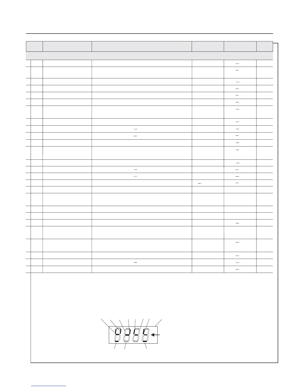
Shown in figure : multi-function terminal X1 X2 X4 X5 FWD input and OC1 relay output is enabled , others
are disabled . Digital has four constant ON segment for observe expediently .
、、、、 、
The information of display terminals contains multi-function terminal from X1 to X6 FWD REV double direction open
collector output OC1 and OC2 and relay output terminal state , it adopt LED digital designed segment ON / OFF indicates every
function terminal state , digital segment ON indicates corresponding terminal state is enabled ,contrarily, it is disabled .
、、、
,
Constant ON segment
for observ ngiexpediently
REV
relay
FWD
X6X5
X4
OC2
X3
Display mode of terminal status parameter FV.15 / F8.16 ):
OC1
X2
X1
Factory default
value
Modif-
ication
Function
code
Name
Setup range
Minimum unit
Chapter 5 Function Parameter Table
Terminal status indication
 Loading...