0
Straight V/F curve
1
Multiple-point V/F curve
2
Square V/F curve 1 (1.5 time power)
3
Square V/F curve 2 (2.0 time power)
0 Straight V/F curve . It is suitable for common constant torque
load .
:
1 Multiple-point V/F curve . It is suitable for the special loads
such as dehydrator and centrifugal machine .
:
2or3:Square V / F curve 1 or 2 .It is suitabled for the centrifugal
loads such as fan and pump .
。
V1 V3~
V2 100.0~%
There are six parameters F2.01 to F2.06 to define MS V/F curve .
The setup value of V/F curve is generally set in accordance
with the load characteristics of the motor .
Note In case of low frequency , higher setup voltage may
cause over heat and even burning of the motor ,
stall over current or current protection.
:
the inverter
is likely to encounter
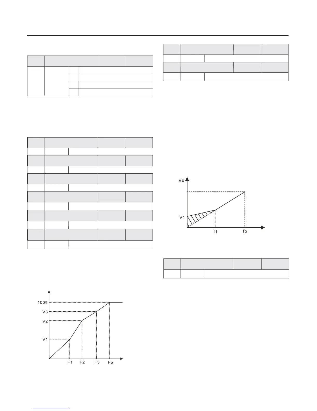
To compensate the low frequency torque characteristics of
V/F control , it can boost the output voltage of the inverter at
the time of low frequency .
If the torque boost is set to be too large , the motor may be over
heat , and the inverter may be over current .
Adjust this parameter effectively can avoid over current upon
startup . For the relatively large loads , it is recommended to
increase this parameter . For the small loads , this parameter
value could be reduced .
Cutoff frequency of torque boost: Under this frequency , the
torque boost is enabled . If it exceeds this setup frequency ,
the torque boost is disabled .Refer to figure for details .
Group F2
V/F Control Parameters
Setup range
Setup range
Setup range
Setup range
Setup range
Setup range
Setup range
F2~
Motor rated frequency
0.
0Hz
~
F2
0. 0%~
V2
~
F1
F3
It is active only for V/F control . Set this parameter can
compensate the slip in the V/F control mode due to load
and reduce the of the motor
with the variety of the load . In general ,
100% corresponds to the rated slip of the motor with rated
load . Slip coefficient adjustment can refer to the following
principles: When the load is rated load and the slip
compensation coefficient is set to 100% , the velocity
of the motor in the inverter is close to the reference velocity .
variation rotation velocity
which is change
rotation
If the actual rotation velocity is lower than the reference
velocity ,the coefficient should be increased accordingly and
vice versa .
46
F2.00
V/F curse setup
0
F2.01
V/F frequency point F1
0. 00Hz
F2.02
V/F voltage point V1
0. 0%
F2.03
V/F frequency point F2
F2.04
V/F voltage point V2
F2.05
V/F frequency point F3
F2.06
V/F voltage point V3
25.00Hz
50.00Hz
50.0%
100.0%
When the torque boost is set to 0% , the inverter will adopt
automatic torque boost .
Chapter 6 Parameter Description
Factory
default value
Factory
default value
Setup range
Setup range
0.0
0.0
20.0%
Hz~
~
rated frequency
50.00Hz
F2.07
Torque boost
F2.08
Cutoff frequency of
torque boost
Model
dependent
Factory
default value
Factory
default value
Factory
default value
Factory
default value
Factory
default value
Factory
default value
Factory
default value
0~
200%
Setup range
F2.09
Slip compensation
coefficient
0%
Factory
default value
Voltage%
Frequency Hz
V1-V3:
F1-F3:
Fb:
Segments 1 to 3 Voltage Proportion MS V/F
Segments 1 to 3 Frequency Point of MS V/F
Rated Motor Frequency F1.04
Fig .6-2 Schematic Diagram for V/F Curve Setup
Output voltage
Output frequency
V1 Manual Torque Boost Voltage
f 1 Cutoff Frequency of Torque Boost
:
:
Vb Rated Output Voltage
f b Rated Frequency
:
:
Fig .6-3 Schematic Diagram for Manual Torque Boost
 Loading...