54
Deceleration to stop
1 Coast to stop
0 deceleration to stop:
After the inverter receives the stop command , the inverter
reduces the output frequency in accordance with the
deceleration mode and stops after the frequency reduces to
zero .
1 coast to stop:
After the stop command is enabled , the inverter will terminate
the output immediately . The load will coast to stop according
to the mechanical inertia .
0
0. 0Hz~Maximum frequency
0.0 36.0s~
0 100%~
0.0 36.0s~
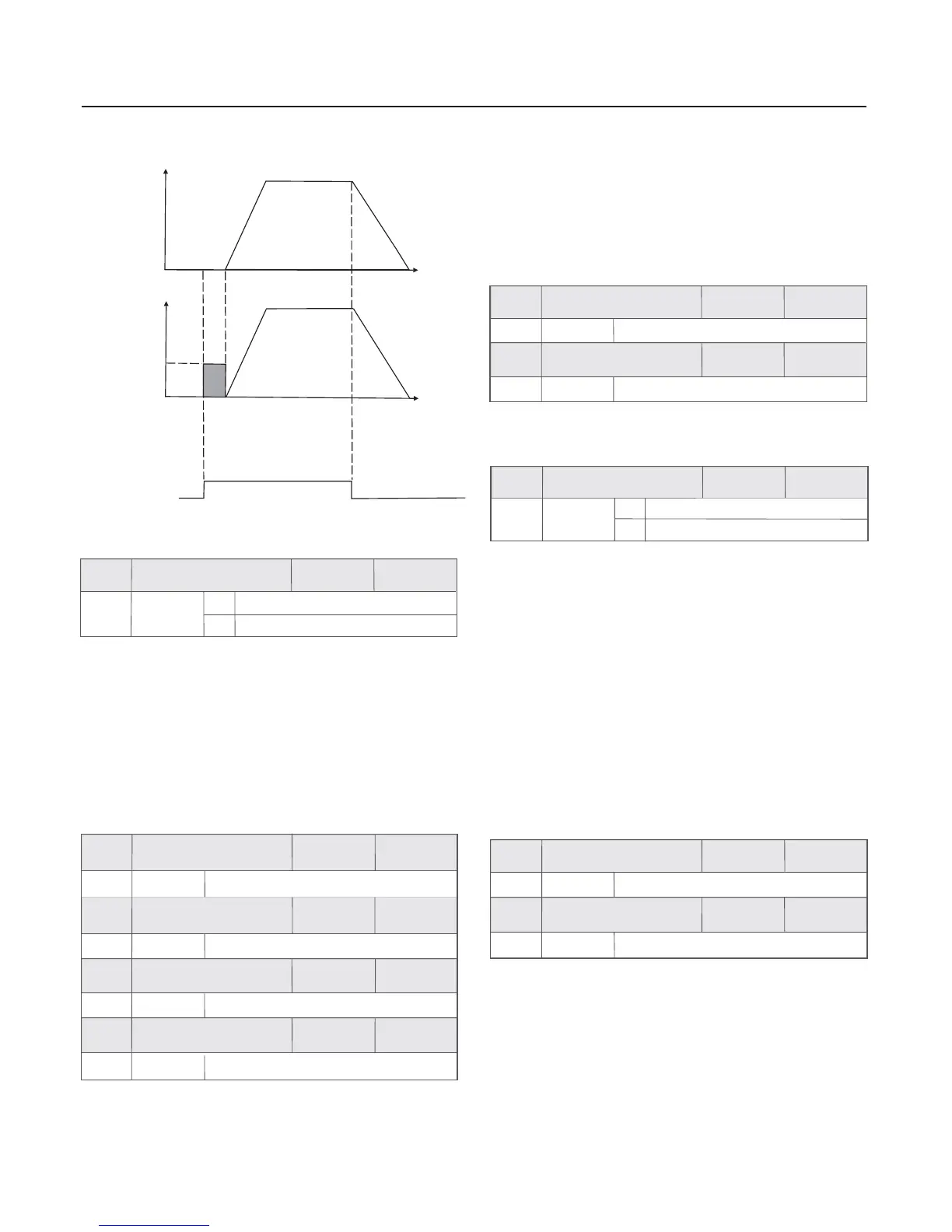
During the deceleration to stop , when the running frequency
reaches DC brake beginning frequency , and
the DC brake quantity has been
until DC brake time at stop (F5.09) finished .
after DC brake
waiting time at stop (F5.07),
inflicted
Inverter has no output during the DC brake waiting time at stop.
As the setup time can prevent the
over-high current at the brake beginning moment.
for high-power motor,
The setup of DC brake current at stop is relative to the percentage
of rated current of inverter . The higher the value is , the better the
DC brake effect is .
When the DC brake time at stop is 0.0s there is no DC brake
process .
,
Fig.6-12 Schematic Diagram for DC Automatic Start Mode
Output
frequency
Output
voltage
DC brake
quantity
DC
brake
time
Running
command
Time
Time
Stop mode
0
F5.05
0.00Hz
0.0s
0%
0.0s
F5.06
F5.07
F5.08
F5.09
Chapter 6 Parameter Description
The process of DC brake is shown as the following figure:
Factory
default value
Factory
default value
Factory
default value
Factory
default value
Factory
default value
Setup range
Setup range
Setup range
Setup range
Setup range
DC brake time at stop
DC brake waiting time
at stop
DC brake current
at stop
DC brake beginning
frequency at stop
30.0%
130%
%40
%
1
~
001
15
~
1
0
F5.10
F5.11
Factory
default value
Factory
default value
Setup range
Setup range
Beginning voltage of
dynamic braking
Use ratio of dynamic
braking
It is enabled for the inverter with built-in brake unit . It can be used
to adjust the brake effect of the brake uint .
0
Straight acceleration/deceleration
S-curve acceleration/deceleration
0
1
Acceleration/
deceleration mode
F5.12
Factory
default value
Setup range
The output frequency increases or decreases along with the
straight line .The acceleration/deceleration time varies with the
setup acceleration/deceleration time .Our company provides four
types of acceleration/deceleration time . It can select
acceleration/deceleration time by the multifunctional digital
input terminals (F3.00 to F3.04).
The output frequency increases or decreases along with the
S curve. S curve is generally used in the applications where
the start and stop are relatively flat , such as elevator
and conveyor belt . Refer to F5.13 and F5.14 for the meanings
of the parameters .
process of
It is used to select the frequency changing mode during the
inverter’s start and stop process .
1 S-curve acceleration/deceleration:
0 straight acceleration /deceleration:
30.0%
30.0%
0.0 40.0%~
0.0 40.0%~
Start segment
proportion of S curve
End segment
proportion of S curve
F5.13
F5.14
Factory
default value
Factory
default value
Setup range
Setup range
t1 in the following figure is the parameter defined in F5.13 ,
within which the output frequency
increases gradually .t2 is the time defined in F5.14 , within
which the slope of the output frequency gradually
decreases to zero . Within the time between t1 and t2 , the
slope of the output frequency remains fixed .
change slope of the
change
change
 Loading...