Chapter 6 Parameter Description
44
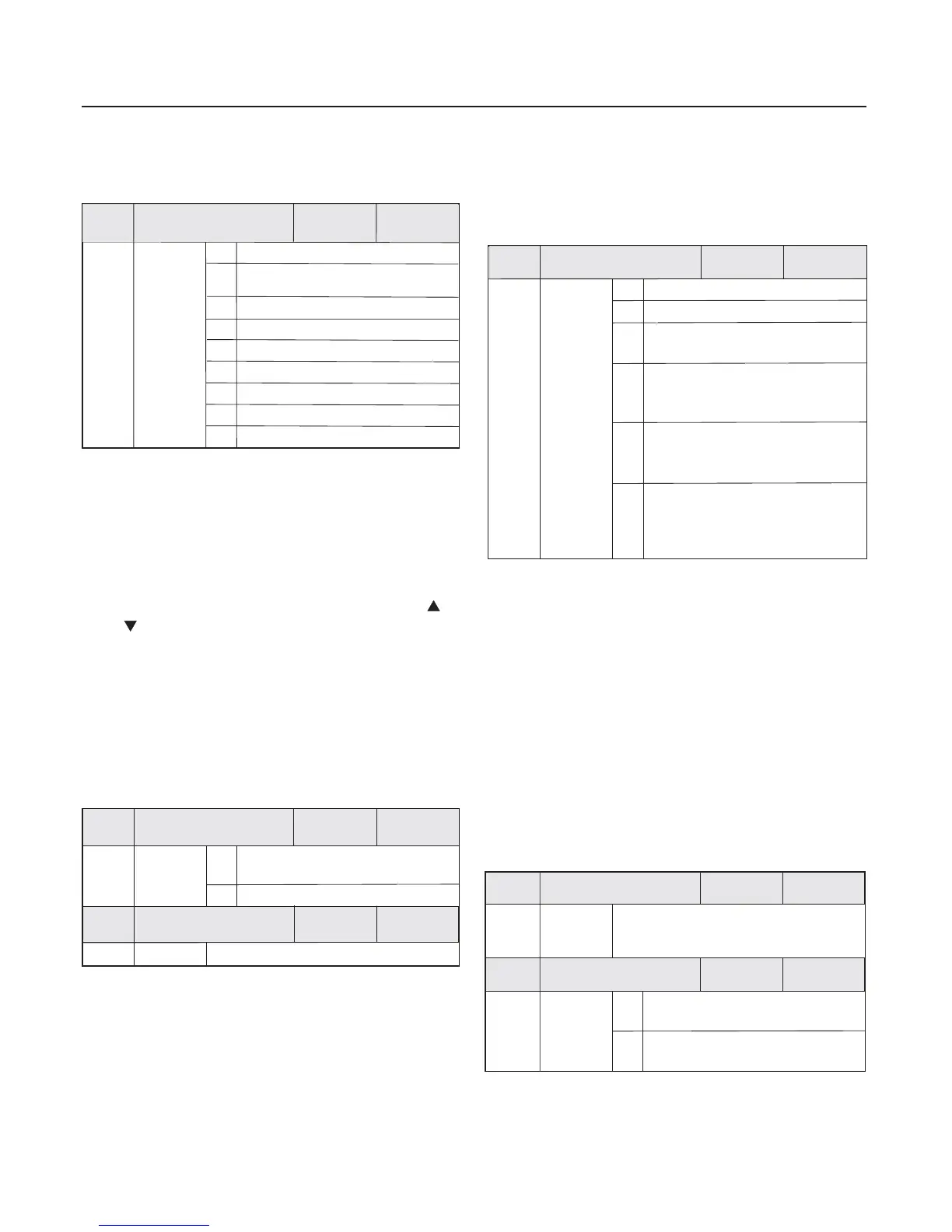
8 Communication reference、
It means that the main frequency source is given by the host
computer via the communication mode .
When the auxiliary frequency source is used as independent
frequency reference channel , its usage is as the same way as
that of the main frequency source .
When the auxiliary frequency source is used as overlap
reference , it has special points as follows
:
Setup range
0
Panel potentiometer
1
2
AI1
3
AI2
Factory
default value
2
Auxiliary frequency
source Y selection
F0.04
Digital setup by UP and DW adjustment
(panel or external terminal)
PLC
PID
Communication reference
MS speed
PULSE setting(DI)
4
5
6
7
8
1:When the auxiliary frequency source is digital reference ,
the preset frequency F0.08 has no action , and it can be
adjusted on the base of the main reference frequency by the keys
and ” (or UP and DW terminals ) .
()
“”
“
When the frequency source selection is frequency overlap
reference F0.07 is set to 2 it is used to determine the
adjustment range of auxiliary frequency source . F0.05 is
used to determine the relative object of that range . If it is
relative to upper limit frequency F0.11 , this rangeis a fixed
value ; if it is relative to main frequency source X ,
this range will vary along with the variety of the main
frequency X .
(),
well then
When the frequency source selection is auxiliary frequency
source Y F0.07 is set to 1 and F0.05 is set to 1 , simple
and convenient control can be realized through
setting the main frequency source X as the main frequency
standard and the auxiliary frequency source as the synchronous
coefficient to make corresponding setup .
()
synchronous
2:When the auxiliary frequency source is analog input
reference
()AI1 and AI2 or pulse input reference , the 100%
of input setup is relative to the auxiliary frequency source range
( refer to F0.05 and F0.06 ) . If adjust on the base of the main
reference frequency , please set the corresponding setup
range of analog input into -n% to +n% (refer to F3.08 to F3.15).
3:When the frequency source is pulse input reference , it is
similar to the analog value .
100%
0
Relative to upper limit
frequency F0.11
Relative to frequency source X
Auxiliary frequency
source Y range selection
0%0
Auxiliary frequency
source Y range
~ 1
0
1
0
5
6
0
0
0.
0.
F
F
Factory
default value
Factory
default value
Setup range
Setup range
F0.07
Frequency source
selection
0
Factory
default value
Setup range
0 Main frequency source X
1
Auxiliary frequency source Y
2
Main frequency source X plus
auxiliary frequency source Y
Switching between main frequency
source X and auxiliary frequency
source Y
3
Switching between main frequency
source X and (main frequency source
X plus auxiliary frequency source Y )
4
Switching between auxiliary
frequency source X and (main
frequency source X plus auxiliary
frequency source Y )
5
This parameter is used to select the frequency
reference channel . Frequency reference is realized
by the combination of the main frequency source X and
the auxiliary frequency source Y .
When 2 is selected it can realize frequency overlapping
function .
,
When 3 or 4 or 5 is selected, the frequency source switching
is realized by the X input terminal frequency source
switching function .
“
”
In this way ,mutually switching between the frequency
reference modes can be realized, for example, switching
between PID running and common running , switching
between simple PLC and common running , switching
betweenpulse setup and analog setup , and switching
between analog setup and common running .
Factory
default value
F0 08
Preset frequency
50.00Hz
.
Setup range
0 .0Hz
~
upper limit frequency F0.11
enabled when the frequency source
selection mode is digital setup
(
)
0
F0.09
Factory
default value
Preset frequency control
Setup range
0
Setup frequency with memory when
power failure
1
Setup frequency without memory
when power failure
When the main frequency source is selected as Digital
setup or Terminals UP/DW this function code is
the initial value of frequency digital setup of the inverter .
“
”“ ”,
 Loading...