ML605 Hardware User Guide www.xilinx.com 49
UG534 (v1.2.1) January 21, 2010
Detailed Description
User Pushbutton Switches
The ML605 provides six active-High pushbutton switches:
• SW5, SW6, SW7, SW8 and SW9, arranged in a diamond configuration to depict
“directional” headings North, South, East, West and Center respectively
• SW10 CPU Reset pushbutton
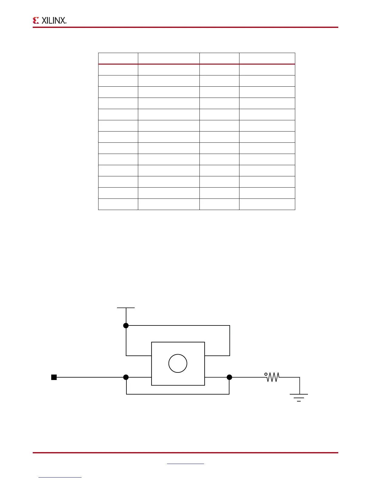
The six pushbuttons all have the same active-High topology as the sample shown in
Figure 1-19. The five directional pushbuttons are assigned as GPIO and the sixth is assigned
as CPU_RESET. Figure 1-19 and Table 1-22, page 50 describe the pushbutton switches.
Table 1-21: User LED Connections
FPGA U1 Pin Schematic Net Name GPIO J62 Pin Controlled LED
AC22 GPIO_LED_0 1 DS12
AC24 GPIO_LED_1 2 DS11
AE22 GPIO_LED_2 3 DS9
AE23 GPIO_LED_3 4 DS10
AB23 GPIO_LED_4 5 DS15
AG23 GPIO_LED_5 6 DS14
AE24 GPIO_LED_6 7 DS22
AD24 GPIO_LED_7 8 DS21
AP24 GPIO_LED_C – DS16
AD21 GPIO_LED_W – DS17
AE21 GPIO_LED_E – DS19
AH28 GPIO_LED_S – DS18
AH27 GPIO_LED_N – DS20
X-Ref Target - Figure 1-19
Figure 1-19: User Pushbutton Switch (Typical)
CPU RESET
VCC1V5
Pushbutton
1
4.7K
R401
5%
1/16W
sw10
2
4
3
1
2
P1
P2
P4
P3
UG534_19_072109

 Loading...


