Platform Cable USB II
DS593 (v1.2.1) March 17, 2011 www.xilinx.com
17
Direct SPI
Platform Cable USB II can connect directly to a single SPI flash device. Figure 18, page 18 shows an example SPI flash
connection. XAPP951
, Configuring Xilinx FPGAs with SPI Serial Flash provides additional details of the cable connections
necessary to program a FPGA bitstream into a SPI flash device.
Note:
See Configuring Xilinx FPGAs with SPI Serial Flash for a list of supported SPI devices.
By connecting PGND to PROG_B of the FPGA (Figure 17), the FPGA can be commanded to set its SPI signals to high-Z
while the cable programs a SPI flash device. PGND is pulled Low when the cable is driving its SPI signals in SPI mode and
set to high-Z when the cable is not driving its SPI signals. PGND eliminates the need for a hardware jumper to ground on the
PROG_B signal and the need for additional control logic. PGND is controlled by an open-drain driver.
Note:
PGND control for SPI programming is available in iMPACT versions 9.2i and later.
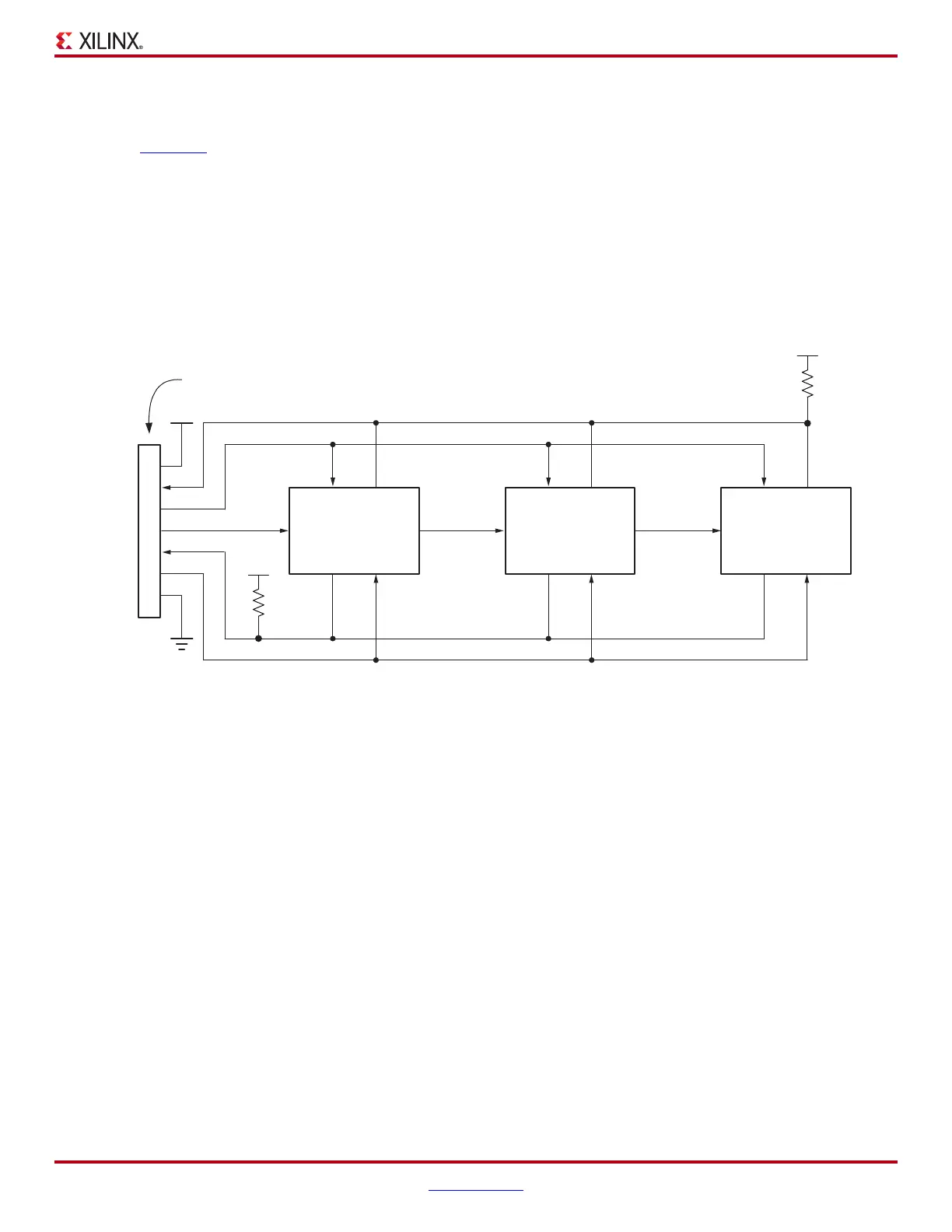
X-Ref Target - Figure 17
Notes:
1. Set Mode pins (M2-M0) on each FPGA to Slave-Serial mode when using the USB cable, so the CCLK is treated as an input.
2. Example uses generalized nomenclature for the voltages-supply levels. Refer to the device data sheet for the appropriate serial configuration
voltage-supply levels.
3. Attach the following 2-mm connector pins to digital ground: 3, 5, 7, 9, and 11.
4. A pull-up is required when two or more devices are cascaded and programmed for open-drain operation.
Figure 17: Example of Cascaded Slave-Serial Topology
FPGA
1
FPGA
2
FPGA
n
DOUTDIN
CCLK
(1)
DONE
INIT
DOUTDIN
CCLK
(1)
DONE
INIT
DOUTDIN
CCLK
(1)
DONE
INIT
INIT
CCLK
DIN
DONE
PROG PROGPROG
PROG
V
CCAUX
(2)
V
CCAUX
(2)
V
CCO
(2)
GND
(3)
V
REF
2
6
4
10
14
8
*
2-mm Connector
DS593_17_021408
470Ω
(4)

 Loading...


