VESDA by Xtralis VESDA PipeNetwork Design Guide
www.xtralis.com 29
6 Plan and Map a Pipe Network
In planning a pipe network, you must:
l Have an understanding of the area to be protected
l Understand the environmental conditions of the protected area
l Identify any forced air ventilation and air flows (fans, air conditioners etc.)
l Take into account any customer specifications
l Determine if the design needs to address:
l Return air grille sampling
l Make use of ceiling and under floor voids
l Consideration for high ceilings, stratification effect and containment aisles
l Any requirement for focused detection
The pipe network grid is mapped on to the construction drawings. The objective of mapping the pipe network
is to determine the placement of sampling holes and to optimize the location of the VESDA detector with a
view to minimizing the pipe length. While mapping the pipe network care should be taken to minimize the
number of bends and elbows used. We recommended that multiple pipes are used in preference to changes in
pipe direction. Refer to Figure 10-1 on page 43.
6.1 Grid Overlay
The Grid Overlay method is utilized to map the pipe layout and determine the position of sampling holes. The
dimensions of the grid depend upon the required maximum or minimum sampling point separations and the
required distance of sampling holes from the walls, which are usually defined by local codes and standards.
Ideally the aim should be a square grid, however, the measurements and the shape of the area to be covered
will determine the grid.
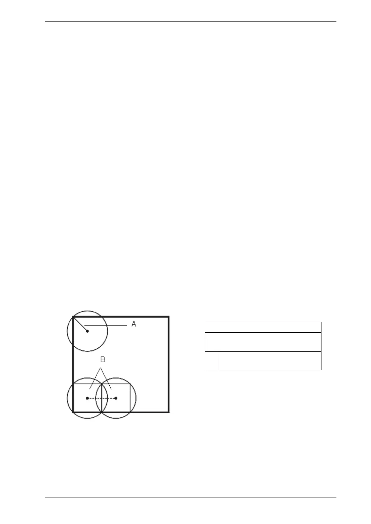
Plot the first sampling hole in a manner that it does not exceed the maximum spacing as dictated by local
codes and standards, or by installation requirements. Typically the maximum distance is likely to be to the
corner of the room.
Note: The spacings imposed by your local codes and standards may well be related to the cost of
conventional point detectors. With the VESDA system it is possible to substantially increase the
density of sampling points at negligible cost. Grids of 4 m X 4 m (13 ft X 13 ft), 6 m X 6 m (20 ft X 20
ft), or 4 m X 8 m (13 ft X 26 ft) are popular choices.
Legend
A Maximum distance of sampling hole
from the wall. (Max 5.1m or 16ft)
B Spacing between sampling holes
(Max 10.2m or 32ft)
Figure 6-1: Illustration of plotting sampling holes and spacing between holes

 Loading...