VESDA by Xtralis VESDA Commissioning Guide
www.xtralis.com 9
4 System Configuration and Setting Thresholds
Different detectors are configured in different ways.
For VESDA VLP, VESDA VLS and VESDA VLC please use the instructions for Generic Configuration in
Section 4.1. Once you have completed these steps you can configure the settings specific to each detector.
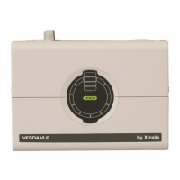
The VESDA VLF was designed with ease of configuration in mind. No specialized hardware or software tools
are required to configure this detector as it will autolearn about its environment once it is installed.
The VESDA VFT-15 is covered in Section 4.3 on page 15.
4.1 Generic Configuration (VLC, VLS, VLP)
When the system is powered up for the first time, any LCD Programmer or PC Software connected to
VESDAnet will register all the detectors and display modules as unconfigured. All other VESDA laser range of
products will appear under ancillary devices. Each laser device has a built in unique number and this number
is displayed next to the device.
For detailed explanation of the LCD Programmer Screens, and the Xtralis VSC Forms and Tabs mentioned in
the table below, please refer to the LCD Programmer Guide and the Xtralis VSC Online Help respectively.
Setting Date and Time
l For LCD Programmer: See LCD screen 144
l For Xtralis VSC: See VESDAnet Form Clock Set Tab
Setting Units
l For LCD Programmer: See LCD screen 157 and select SI (for International System of Units) or US (for
US Imperial measurements)
l For Xtralis VSC: See VESDAnet Form Units Tab
Configuring a Detector to a VESDA Zone
For LCD Programmer:
l See LCD screen 4 to select a detector
l See LCD screen 21, 41 & 91 to assign a VESDA zone number to the detector
l See LCD screen 22, 4, 2, 92 to assign an address name and/or location
More experienced technicians prefer to use the Drag and drop function.
For Xtralis VSC:
1. Press insert, then drag and drop the devices into their respective addresses
2. Select Address name/location tab and enter a suitable name/location for the detector
Assigning a display module to a detector
For LCD Programmer: See LCD screen 110
1. Select the relevant display module.
2. Give it the same address number as the assigned detector
3. Enter the address name/location of the display
For Xtralis VSC: Select Device Tree/Menu
1. Select the display on the device tree
2. Select address Configuration Tab to enter the address number
3. Select address name/location tab and enter respective address name/location
Reference detector configuration
For LCD Programmer: See LCD screen 28, 67, 97
1. Give a reference address number or enter 255 if there is no reference detector.
2. Set the dilution factor
3. Set the delay time
 Loading...
