DANGER: Explosion/Fire Hazard
Special rules apply to installations in explosive or flammable atmospheres. Do not install
the product or any auxiliary equipment in an explosive zone unless it is rated explosion-
proof or intrinsically-safe. If the product is EN/ATEX-, MSHA- or FM-approved, then see
the specific EX information in the Safety chapter before taking any further actions.
Three thermal contacts are incorporated in the stator. They are normally closed.
Thermal contacts must never be exposed to voltages higher than 250 V, breaking current
maximum 6 A at a power factor 0.6. It is recommended that the thermal contacts are
connected to 24 V over a separate fuse to protect any other automatic equipment.
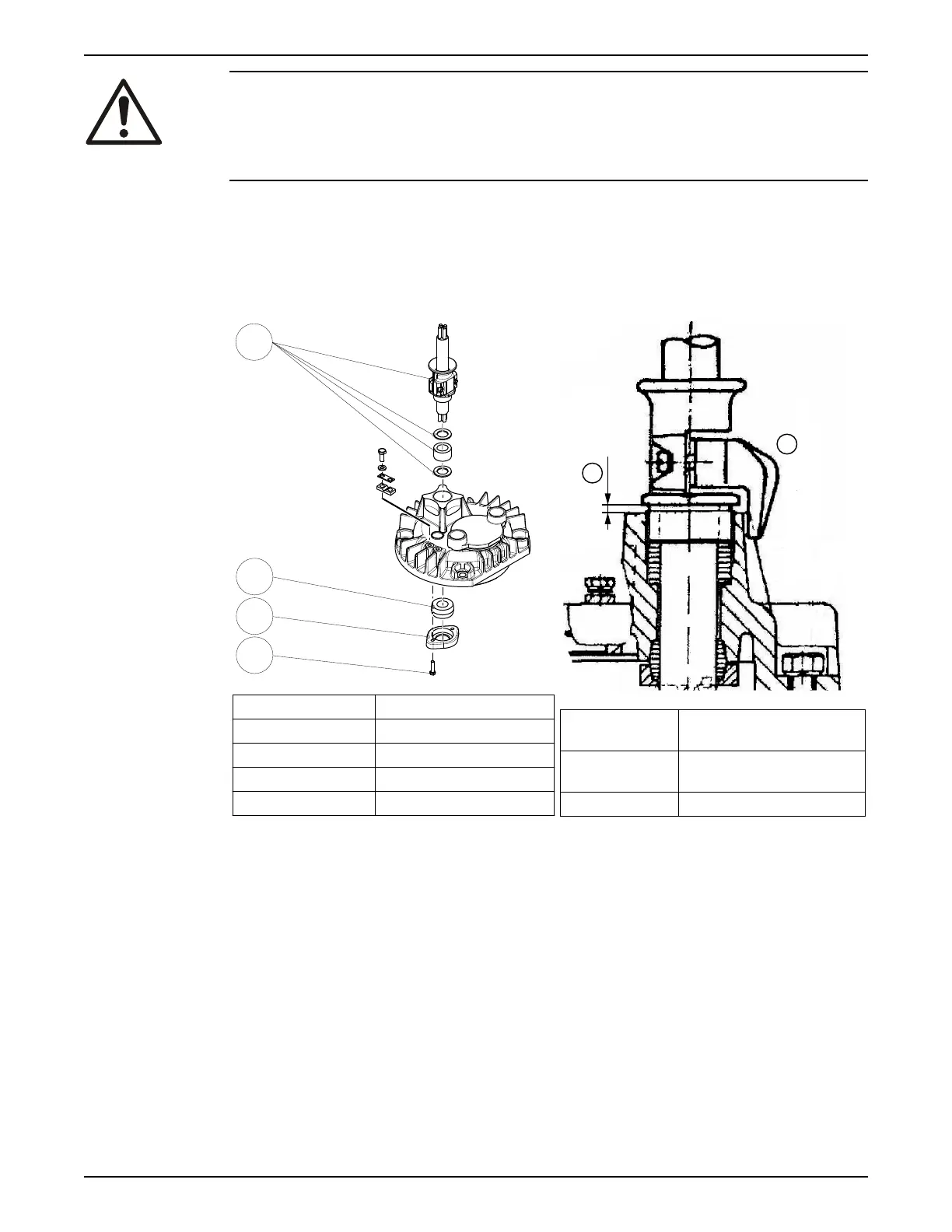
4.2.3 Connect the motor cable to the pump: Version code 590/690/691
Position number
Description
5 Hexagon head screw
90 Cable entry
92 Gland flange
93 Seal sleeve
Figure 9: Cable entry
Position
number
Description
1 Minimum clearance
3.2 mm (0.13 in)
2 Cable strain relief
Figure 10: Cable strain relief
1. Insert the motor cable.
25–30 mm (0.9–1.2 in) of the jacket must be on the inside of the cover.
2. Check that the seal sleeves and washers conform to the outside diameter of the cable.
3. Tighten the cable entry so that the seal sleeve is compressed and seals between the
motor cable and the cover.
Leave a clearance between the cover and the flange on the cable entry. See Figure
10: Cable strain relief (page 22).
The cable entry is threaded with Pg29/Pr37, Pg36/Pr47, and Pg42/Pr54.
4. Twist together the ground (earth) leads into a bundle and slip an insulating tube over
the intertwined leads.
The ground (earth) leads are located concentrically around each phase lead.
5. Fit the gland flange:
4 Installation
22 Flygt 2190, 2201 Installation, Operation, and Maintenance Manual
 Loading...