a) Fit it with the largest diameter of the hole facing the inside of the cover.
b) Tighten the screws, but leave 1 mm (0.04 in) of clearance between the cover and
the gland flange.
6. Fit the O-ring on the cover.
7. Connect the leads.
8. Connect the control cable between the terminal board (H1 and H2) and the control
circuit of the starter.
9. Fit and tighten the cover.
Check, through the inspection hole, that no leads are pinched.
10. Fit the O-ring on the inspection cover.
11. Fit and tighten the inspection cover.
12. Fit and tighten the cable strain relief on the cable entry.
13. Connect the pump to ground (earth) with an external ground (earth) lead on the top
of the cover.
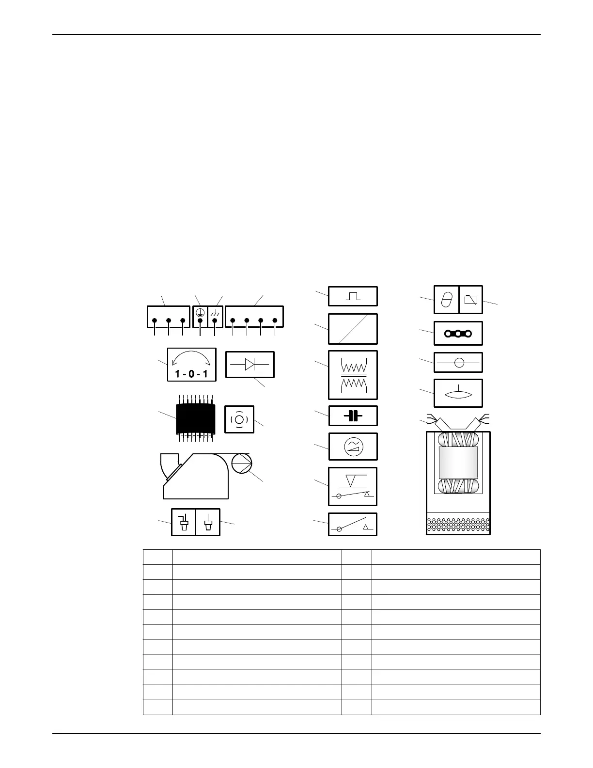
4.2.4 Cable charts
Connection locations
WS001021B
L1 L2 L3
T3 T4T1 T2
15
13
14
42 31
7
10
5
9
8
6
11
12
17
16
24
22
23
19
20
21
18
1 Starter equipment and main leads (L1, L2, L3) 13 Coil
2 Ground (earth) 14 Transformer
3 Functional ground 15 Capacitor
4 Control leads (T1, T2, T3, T4) 16 Softstarter
5 Phase shifter 17 Level regulator
6 Diode 18 Contactor, start relay or thermal relay
7 Motor cable 19 Thermal detector in stator
8 Screen 20 Thermal detector in main bearing
9 Pump 21 Jumper
10 Crimp connection 22 Terminal board, terminal plate
11 Crimp isolation 23 Leakage sensor
4 Installation
Flygt 2190, 2201 Installation, Operation, and Maintenance Manual 23
 Loading...