FT-891 Technical Supplement
Alignment
ALIGNMENT-8
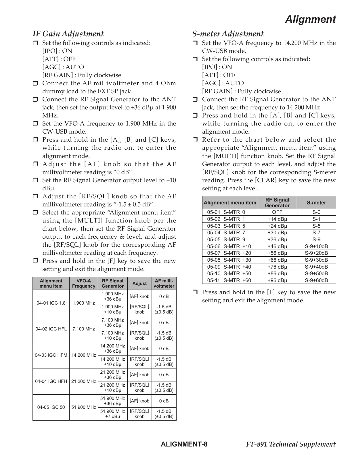
IF Gain Adjustment
Set the following controls as indicated:
[
IPO
]
: ON
[
ATT
]
: OFF
[
AGC
]
: AUTO
[
RF GAIN
]
: Fully clockwise
Connect the AF millivoltmeter and 4 Ohm
dummy load to the EXT SP jack.
Connect the RF Signal Generator to the ANT
jack, then set the output level to +36 dBμ at 1.900
MHz.
Set the VFO-A frequency to 1.900 MHz in the
CW-USB mode.
Press and hold in the
[
A
]
,
[
B
]
and
[
C
]
keys,
while turning the radio on, to enter the
alignment mode.
Adjust the
[
AF
]
knob so that the AF
millivoltmeter reading is “0 dB”.
Set the RF Signal Generator output level to +10
dBμ.
Adjust the
[
RF/SQL
]
knob so that the AF
millivoltmeter reading is “-1.5 ± 0.5 dB”.
Select the appropriate “Alignment menu item”
using the
[
MULTI
]
function knob per the
chart below, then set the RF Signal Generator
output to each frequency & level, and adjust
the
[
RF/SQL
]
knob for the corresponding AF
millivoltmeter reading at each frequency.
Press and hold in the
[
F
]
key to save the new
setting and exit the alignment mode.
Alignment
menu item
VFO-A
Frequency
RF Signal
Generator
Adjust
AF milli-
voltmeter
04-01 IGC 1.8 1.900 MHz
1.900 MHz
+36 dBµ
[
AF
]
knob 0 dB
1.900 MHz
+10 dBµ
[
RF/SQL
]
knob
-1.5 dB
(±0.5 dB)
04-02 IGC HFL 7.100 MHz
7.100 MHz
+36 dBµ
[
AF
]
knob 0 dB
7.100 MHz
+10 dBµ
[
RF/SQL
]
knob
-1.5 dB
(±0.5 dB)
04-03 IGC HFM 14.200 MHz
14.200 MHz
+36 dBµ
[
AF
]
knob 0 dB
14.200 MHz
+10 dBµ
[
RF/SQL
]
knob
-1.5 dB
(±0.5 dB)
04-04 IGC HFH 21.200 MHz
21.200 MHz
+36 dBµ
[
AF
]
knob 0 dB
21.200 MHz
+10 dBµ
[
RF/SQL
]
knob
-1.5 dB
(±0.5 dB)
04-05 IGC 50 51.900 MHz
51.900 MHz
+36 dBµ
[
AF
]
knob 0 dB
51.900 MHz
+7 dBµ
[
RF/SQL
]
knob
-1.5 dB
(±0.5 dB)
S-meter Adjustment
Set the VFO-A frequency to 14.200 MHz in the
CW-USB mode.
Set the following controls as indicated:
[
IPO
]
: ON
[
ATT
]
: OFF
[
AGC
]
: AUTO
[
RF GAIN
]
: Fully clockwise
Connect the RF Signal Generator to the ANT
jack, then set the frequency to 14.200 MHz.
Press and hold in the
[
A
]
,
[
B
]
and
[
C
]
keys,
while turning the radio on, to enter the
alignment mode.
Refer to the chart below and select the
appropriate “Alignment menu item” using
the
[
MULTI
]
function knob. Set the RF Signal
Generator output to each level, and adjust the
[
RF/SQL
]
knob for the corresponding S-meter
reading. Press the
[
CLAR
]
key to save the new
setting at each level.
Alignment menu item
RF Signal
Generator
S-meter
05-01 S-MTR 0 OFF S-0
05-02 S-MTR 1 +14 dBµ S-1
05-03 S-MTR 5 +24 dBµ S-5
05-04 S-MTR 7 +30 dBµ S-7
05-05 S-MTR 9 +36 dBµ S-9
05-06 S-MTR +10 +46 dBµ S-9+10dB
05-07 S-MTR +20 +56 dBµ S-9+20dB
05-08 S-MTR +30 +66 dBµ S-9+30dB
05-09 S-MTR +40 +76 dBµ S-9+40dB
05-10 S-MTR +50 +86 dBµ S-9+50dB
05-11 S-MTR +60 +96 dBµ S-9+60dB
Press and hold in the
[
F
]
key to save the new
setting and exit the alignment mode.
 Loading...