FT
DX
1200 Technical Supplement
Alignment
ALIGNMENT-18
SWR Meter Adjustment
Set the VFO-A frequency to 1.820 MHz in the
USB mode.
Connect the 50-Ohm Dummy Load and Watt-
meter to the “ANT 1” Jack.
Disconnect the 3-pin plug from J1012 on the
MAIN Unit, then apply a 4.20 ±0.05 V DC volt-
age to pin 2 of J1012, and 0.84 ±0.05 V DC to pin
3 of J1012.
Rotate the [PROC/CAR] knob for Minimum.
Press and hold in the [1.8(1)], [3.5(2)], and [7(3)]
keys, while turning the radio on, to enter the
alignment mode.
Rotate the Main Tuning Dial knob to select the
alignment parameter “23-01 SWR-MTR1.5 1.8”
Press the [MOX] buon, then rotate the [VFO-B/
CLAR] knob so that the SWR meter (on the
front panel) reading is “1.5”. The SWR meter
reading (1.5) is broad (few points). Therefore,
set the [VFO-B/CLAR] knob to the center of this
broad range.
Release the [MOX] buon.
Apply a 4.20 ±0.05 V DC voltage to pin 2 of
J1012, and 1.40 ±0.05 V DC to pin 3 of J1012.
Rotate the Main Tuning Dial knob to select the
alignment parameter “23-02 SWR-MTR2.0 1.8”
Press the [MOX] buon, then rotate the [VFO-B/
CLAR] knob so that the SWR meter (on the
front panel) reading is “2.0.” The SWR meter
reading (2.0) is broad (few points). Therefore,
set the [VFO-B/CLAR] knob to the center of this
broad range.
Release the [MOX] buon.
Apply a 4.20 ±0.05 V DC voltage to pin 2 of
J1012, and 2.10 ±0.05 V DC to pin 3 of J1012.
Rotate the Main Tuning Dial knob to select the
alignment parameter “23-03 SWR-MTR3.0 1.8”
Press the [MOX] buon, then rotate the [VFO-B/
CLAR] knob so that the SWR meter (on the
front panel) reading is “3.0.” The SWR meter
reading (3.0) is broad (few points). Therefore,
set the [VFO-B/CLAR] knob to the center of this
broad range.
Release the [MOX]buon.
Perform the same procedures for the Alignment
Menus “23-05 SWR-MTR1.5 14” through “23-
07 SWR-MTR3.0 14”, “23-09 SWR-MTR1.5 50”
through “23-11 SWR-MTR3.0 50”.
Note: Please do not change the Alignment Menus
“23-04 SWR-MTR CO 1.8”, “23-08 SWRMTR CO
14” and “23-12 SWR-MTR CO 50”.
These parameters are always 128.
Press and hold in the [MENU] buon for 2 sec-
onds to save the new seings and exit the align-
ment mode.
Connect the 3-pin plug to J1012 on the MAIN
Unit.
Important Notice: If it will be in a transceiver trans-
miing state, without connecting the 3-pin plug
to J1012, there is a possibility that a nal tran-
sistor may break.
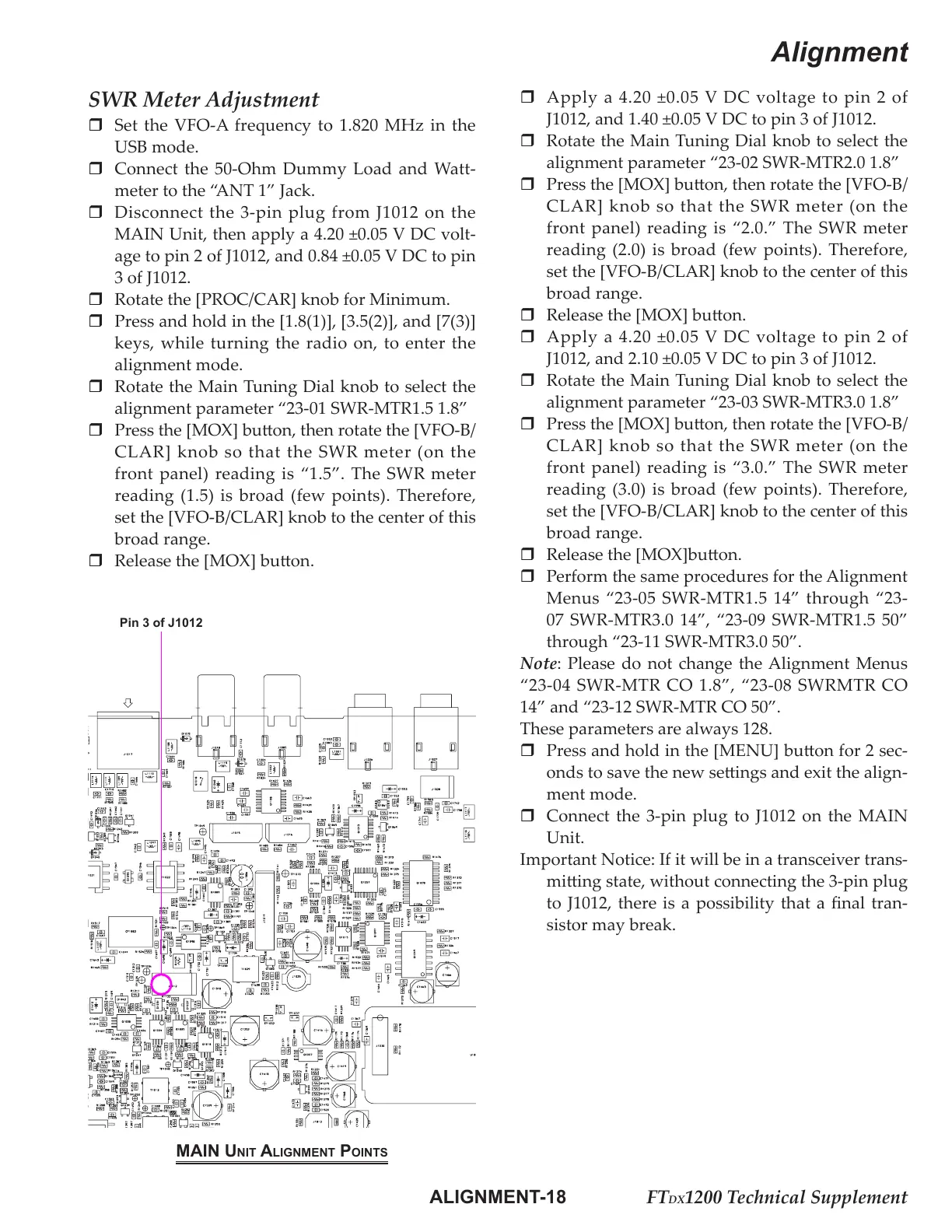
mAin Unit Alignment Points
Pin 3 of J1012

 Loading...