Page 54 FTDX5000 OPERATING MANUAL
The FTDX5000 includes an unmatched array of RF selectivity-enhancing features. Please study the following material
carefully, to understand the many interference tools and techniques completely.
USING THE VRF
(
VARIABLE RF FRONT-END FILTER
)
The VRF system is a high-performance RF front-end preselector that has a high Q factor and low insertion loss. VRF
provides outstanding rejection of out-of-band signals, it can also significantly improve receiver performance when located
near other transmitters, such as a contest or DX-pedition station. The FTDX5000 VRF system affects the 1.8 - 28 MHz
amateur bands only.
A
DVANCED
I
NTERFERENCE
-S
UPPRESSION
F
EATURES
:
RF F
RONT
E
ND
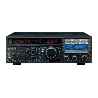
VFO-A VRF Setup
Press the
(
VFO-A
)[
VRF
]
button. The button will glow
red, and the “ ” icon will appear at the FLT col-
umn of the Block Diagram Display. The VRF system
will be engaged and centered on the currently operat-
ing amateur band. The
(
VFO-A
)[
SELECT
]
knob will
now function as the VRF adjusting knob.
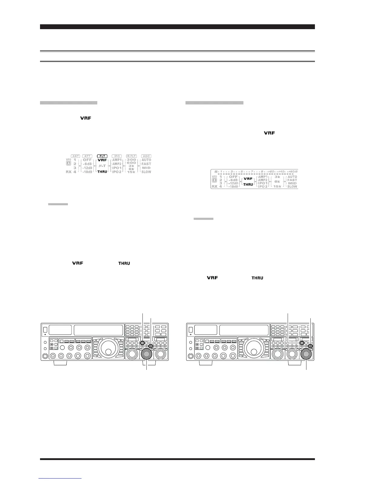
VFO-B VRF Setup
Press the
(
VFO-B
)[
RX
]
button to engage Dual Receive
operation. The button will glow green.
Press the
(
VFO-B
)[
VRF
]
button. The
(
VFO-B
)[
VRF
]
button will glows red, and the “ ” icon will appear
at the FLT column of the Block Diagram Display. The
VRF system will be engaged and centered on the cur-
rent operating amateur band. The
(
VFO-B
)[
SELECT
]
knob will now function as the VRF adjusting knob.
(
VFO-A
)[
SELECT
]
Knob
[
CLEAR
]
Button
(
VFO-A
)[
VRF/μ-T
]
Button
(
VFO-B
)[
SELECT
]
Knob
[
CLEAR
]
Button
(
VFO-B
)[
VRF
]
Button
You may rotate the
(
VFO-A
)[
SELECT
]
knob to
change the VRF system tuning, relative to your oper-
ating frequency.
ADVICE:
You may observe the relative skew of the VRF sys-
tem in the SUB DISPLAY-II. window.
After moving the passband of the VRF system
manually, you may re-center it on the current Ama-
teur band by pressing the
(
VFO-A
)[
CLEAR
]
but-
ton.
To switch VRF off, press the
(
VFO-A
)[
VRF
]
button
until the “ ” icon shows “ ” in the FLT col-
umn of the Block Diagram Display; this confirms that
the VRF circuit has been removed from the incoming
received signal path.
You may rotate the
(
VFO-B
)[
SELECT
]
knob to
change the VRF system tuning, relative to your oper-
ating frequency.
ADVICE:
You may observe the relative skew of the VRF sys-
tem in the SUB DISPLAY-III window.
After moving the passband of the VRF system
manually, you may re-center it on the current Ama-
teur band by pressing the
(
VFO-B
)[
CLEAR
]
but-
ton.
To switch VRF off, press the
(
VFO-B
)[
VRF
]
button.
The “ ” icon shows “ ” in the FLT column of
the Block Diagram Display; this confirms that the VRF
circuit has been removed from the incoming received
signal path.

 Loading...