Page 56 FTDX5000 OPERATING MANUAL
R.FLT
(
ROOFING FILTERS
)
Narrow-band Roofing Filters of 15 kHz, 6 kHz, 3 kHz, 600 Hz
Ú
, and 300 Hz
Ú
bandwidths are provided in the first IF, right
after the first mixer. These filters provide protection for the 2nd mixer, DSP, and other circuitry that follow. The roofing
filter can dramatically improve reception on a very crowded band (during a contest, etc.). Typically, the AUTO selection
mode is satisfactory for most operating situations, but in an extremely crowded phone or CW band you may wish to select
a narrower filter. For example, the 3 kHz roofing filter for SSB operation, or the 600 Hz filter for CW.
Ú
:
The 600 Hz roofing filter is only available on VFO-A. The 300Hz filter for VFO-A on the FTDX5000, is optional on
other versions.
I
NTERFERENCE
R
EJECTION
(
S
IGNALS
O
FF
F
REQUENCY
BY
J
UST
A
F
EW
KHZ
)
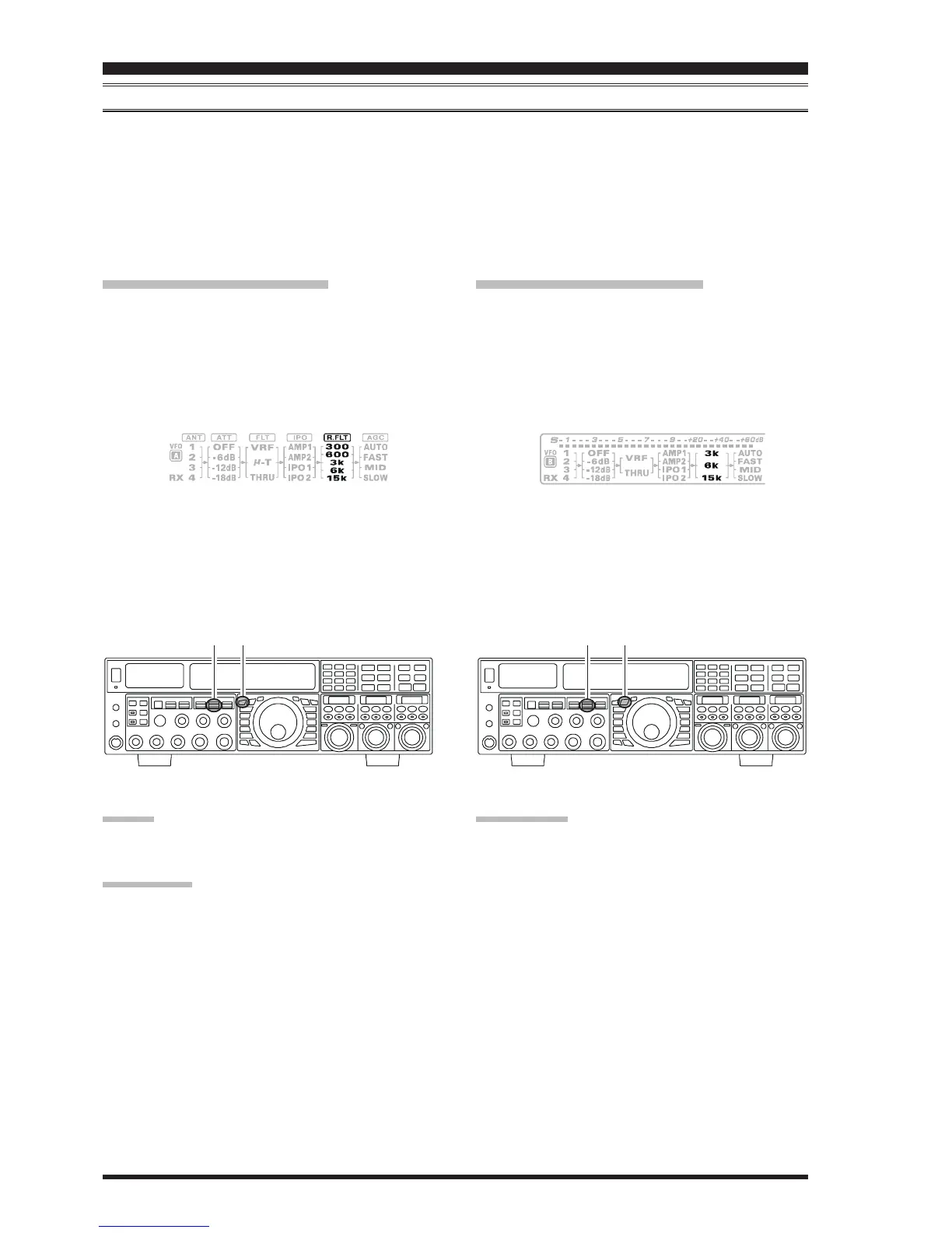
VFO-A Roofing Filter Setup
Press the
[
A
]
button (the button will glow red), to acti-
vate the VFO-A receiver.
Move the
[
R.FLT
]
knob up and down to set the de-
sired bandwidth of the VFO-A Roofing Filter.
The selected bandwidth of the Roofing Filter will be
indicated in the R.FLT column of the Block Diagram
Display.
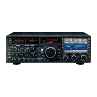
VFO-B Roofing Filter Setup
Press the
[
B
]
button (the button will glow orange), to
activate the VFO-B receiver.
Move the
[
R.FLT
]
knob up and down to set the de-
sired bandwidth of the VFO-B Roofing Filter.
The selected bandwidth of the Roofing Filter will be
indicated in the R.FLT column of the Block Diagram
Display.
ADVICE:
The Roofing Filter selection will be memorized inde-
pendently on each VFO memory in the VFO stack.
QUICK POINT:
The AUTO mode Roofing Filter selections are shown
below:
AM/FM/FM-PKT: 15 kHz
LSB/USB/PKT: 6 kHz
CW/RTTY: 3 kHz
Press the
[
R.FLT
]
knob in briefly, to quickly set the
Roofing Filter to the “AUTO” selection. The filter will
be selected according to the operating mode. The indi-
cated bandwidth will blink for three seconds in the
Roofing Filter Display, and thereafter will appear con-
tinuously. Typically, the filter will be set to “AUTO”,
but may be easily changed when needed.
TERMINOLOGY:
A “Roofing Filter,” as its name implies, places a “Roof”
over the receiver’s IF system bandwidth. This “Roof” pro-
tects the circuitry downstream from strong signal over-
load interference, just as a roof on a house protects the
contents from rain and snow.
[
A
]
Button
[
R.FLT
]
Knob
[
B
]
Button
[
R.FLT
]
Knob
HIJKHIJKHIJKHIJKHIJKHIJKHIJKHIJKHIJKHIJKHIJKHIJKHIJKHIJKHIJKHIJKHIJKHIJKHIJKHIJKHIJKHIJKHIJKHIJKHIJKHIJKHIJKHIJK