Page 59FTDX5000 OPERATING MANUAL
CONTOUR CONTROL OPERATION
I
NTERFERENCE
R
EJECTION
(
S
IGNALS
WITHIN
3
KHZ
)
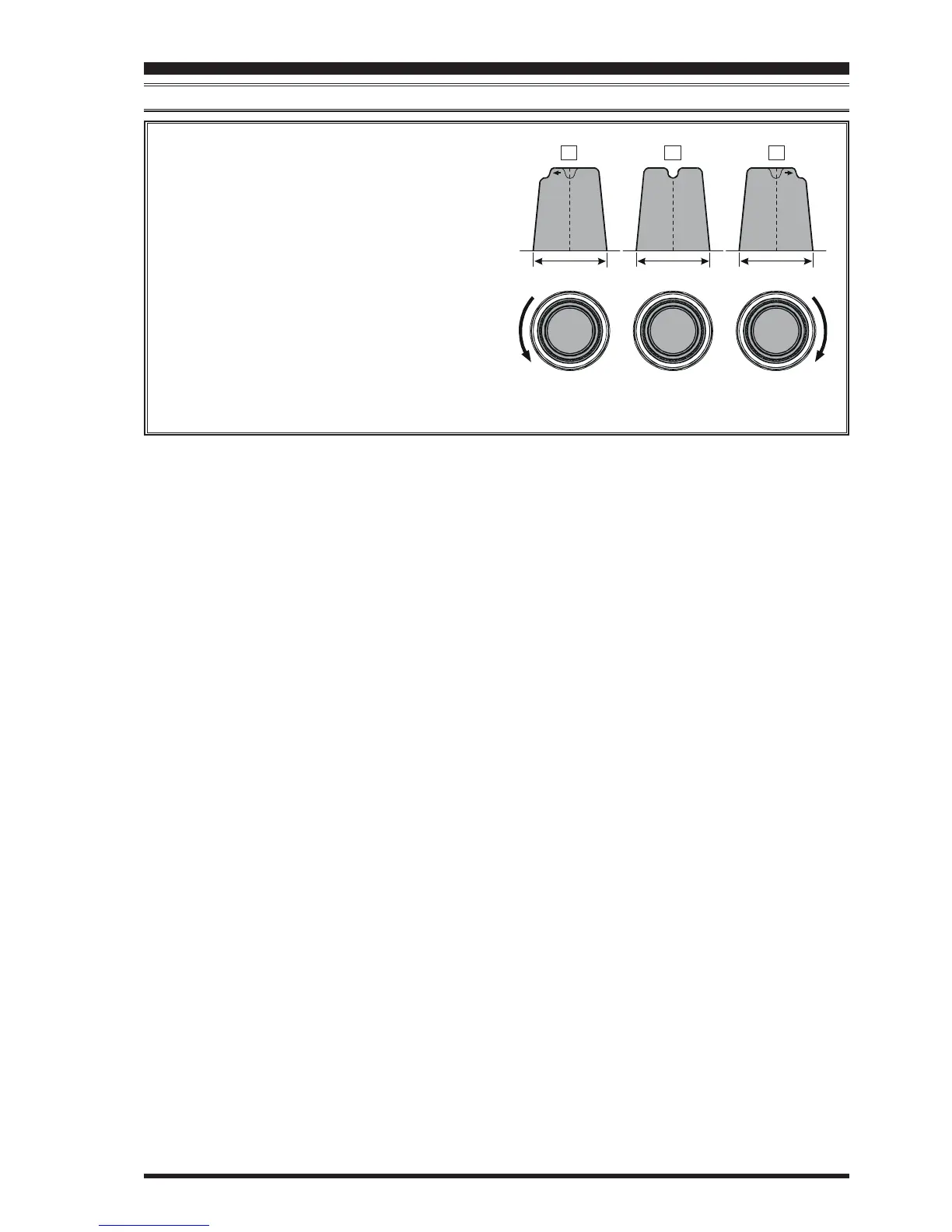
Refer to Figure “B”, and notice the initial position of
the contour when the
[
CONT
]
button is pushed. Ob-
serve the “indentation” in the receiver passband where
the contour filter is placing a low-Q “notch” (accord-
ing to the setting of Menu item “112 RDSP CNTR
LV”, as described on the previous page). Counter-
clockwise rotation of the
[
SELECT
](
contour
)
knob
causes the indentation to move toward a lower fre-
quency (to the left) within the passband, while clock-
wise rotation causes the indentation to move toward a
higher frequency (to the right) within the passband. By
removing the interference or unwanted frequency com-
ponents on the incoming signal, it is possible to make
the desired signal rise out of the background noise/
interference, and significantly enhance intelligibility.
IF
BANDWIDTH
IF
BANDWIDTH
IF
BANDWIDTH
ABC

 Loading...