RX-V661/HTR-6060/DSP-AX761
16
Ground lead
アース線
Ground lead
アース線
FUNCTION (1) P.C.B.
FUNCTION (1) P.C.B.
HDMI P.C.B.
DSP P.C.B.
DSP P.C.B.
Rear panel
リアパネル
Rubber sheet and cloth
ゴムシートと布
MF125400
MF113450
MF116400
CB205
CB61
CB89
PJ201
PJ41
CB5
CB4
G801
CB47
Tuner
チューナー
Ground lead
アース線
Ground point
アースポイント
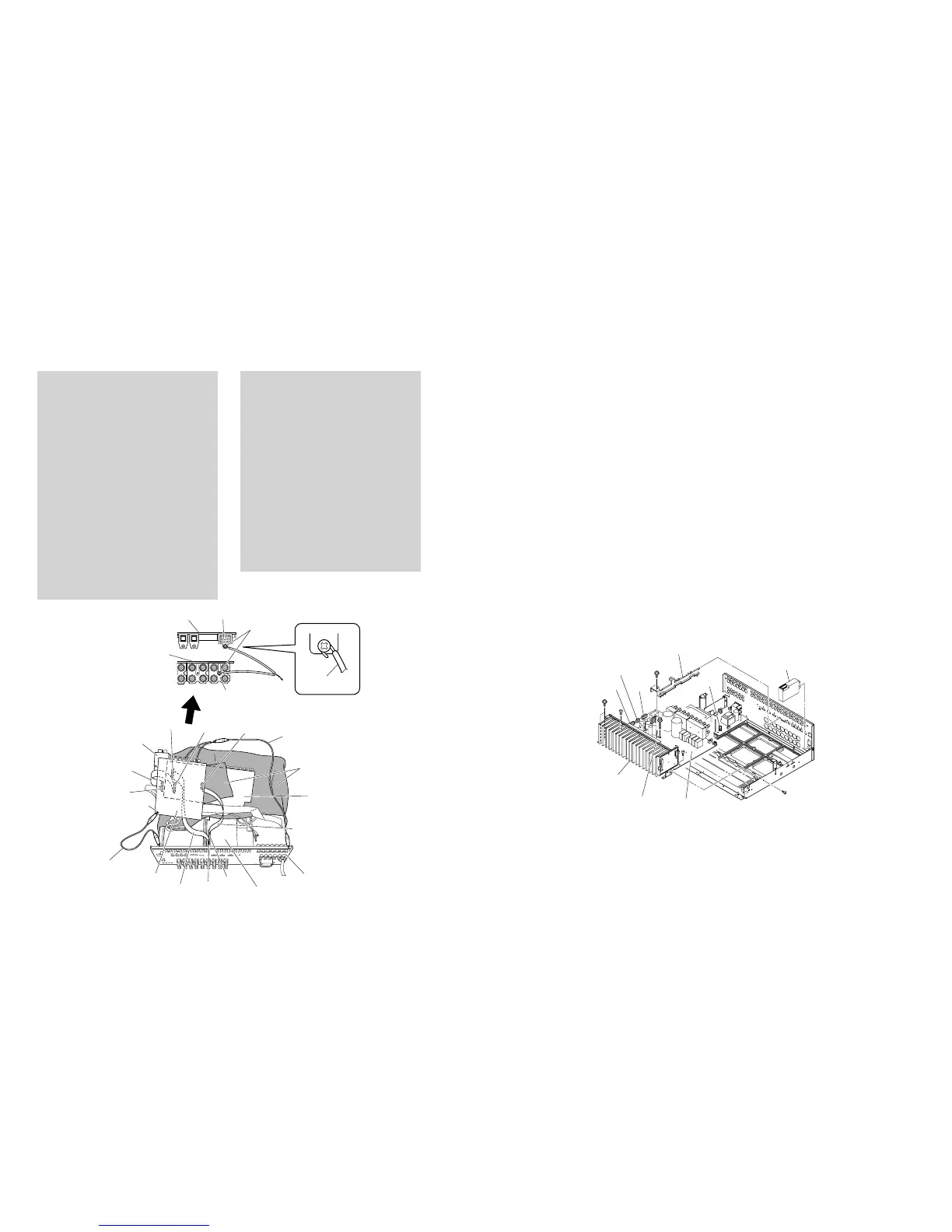
Fig. 5
Fig. 6
Tuner
チューナー
CB251
K
K
L
M
N
I
Artbase E
アートベースE
Heat sink
ヒートシンク
CB101
CB102
(U, C models)
CB100
MAIN (1) P.C.B.
MAIN (2) P.C.B.
When checking the P.C.B.:
• Put the rubber sheet and cloth over the equipment.
Then place the P.C.B.s upside down on the cloth and
check it. (Fig. 5)
• Reconnect all cables (connectors) that have been
disconnected.
Be sure to use the extension cable before replacing
the following section.
DSP P.C.B._CB61 to FUNCTION (1) P.C.B._CB205:
25P, 400mm (Part No. MF125400)
DSP P.C.B._CB47 to HDMI P.C.B._CB4:
16P, 400mm (Part No. MF116400)
DSP P.C.B._CB89 to HDMI P.C.B._CB5:
13P, 450mm (Part No. MF113450)
• When connecting the flexible flat cable, be careful
with polarity.
• In this unit, the ground of P.C.B.s shown below is
connected to the rear panel and chassis.
When these P.C.B.s are removed from the rear panel
and chassis, connect the ground point to the rear
panel or chassis, using a ground lead or such. (Fig. 5)
DSP P.C.B. G801 (Ground)
DSP P.C.B. PJ41 (COAXIAL IN)
FUNCTION (1) P.C.B. PJ201 (AUDIO IN)
P.C.B.チェックをする場合には:
・ 本機の上にゴムシートと布を敷き、その上にP.C.B.を
裏返しに置いてチェックします。(Fig.5)
・ 外したケーブル(コネクター)をすべて接続します。
ただし次の区間は、サービス用延長ケーブルを使用し
てください。
DSPP.C.B.CB61−FUNCTION(1)P.C.B.CB205:
25P、400mm(PartNo.MF125400)
DSPP.C.B.CB47−HDMIP.C.B.CB4:
16P、400mm(PartNo.MF116400)
DSPP.C.B.CB89−HDMIP.C.B.CB5:
13P、450mm(PartNo.MF113450)
・ カード電線を接続する際、極性に注意してください。
・ 本機ではP.C.B.のアースがリアパネルおよびシャーシ
に接続されています。
これらのP.C.B.をリアパネルおよびシャーシより取り
外した場合は、リード線等でアースポイントをリアパ
ネルまたはシャーシに接続してください。(Fig.5)
DSPP.C.B.G801(Ground)
DSPP.C.B.PJ41(COAXIALIN)
FUNCTION(1)P.C.B.PJ201(AUDIOIN)
6. HDMIP.C.B.の外し方
a.
D
のネジ1本を外します。(Fig.3)
b.
E
のネジ5本を外します。(Fig.4)
c. CB7を外します。(Fig.3)
d. HDMIP.C.B.を取り外します。(Fig.3)
7. VIDEO、FUNCTION(2)、(5)P.C.B.の外し方
a.
F
のネジ1本を外します。(Fig.3)
b.
G
のネジ12本を外します。(Fig.4)
c. CB301を外します。(Fig.3)
d. VIDEO、FUNCTION(2)、(5)P.C.B.をアートベースC
と一緒に取り外します。(Fig.3)
8. チューナーの外し方
a.
H
のネジ2本を外します。(Fig.4)
b. チューナーを取り外します。(Fig.6)
9. MAIN(1)、(2)P.C.B.の外し方
a.
I
のネジ1本を外し、アートベースEを取り外します。
(Fig.6)
b.
J
のネジ6本を外します。(Fig.4)
c.
K
のネジ2本、
L
のネジ1本、
M
のネジ2本、
N
のネジ1
本を外します。(Fig.6)
d. CB100、CB101、CB251を外します。(Fig.6)
e. MAIN(1)、(2)P.C.B.をヒートシンクと一緒に取り外し
ます。(Fig.6)
6. Removal of HDMI P.C.B.
a. Remove screw (D). (Fig. 3)
b. Remove 5 screws (E). (Fig. 4)
c. Remove CB7. (Fig. 3)
d. Remove the HDMI P.C.B.. (Fig. 3)
7. Removal of VIDEO, FUNCTION (2) and (5) P.C.B.s
a. Remove screw (F). (Fig. 3)
b. Remove 9 screws (G). (Fig. 4)
c. Remove CB301. (Fig. 3)
d. Remove the VIDEO, FUNCTION (2) and (5) P.C.B.s
together with artbase C. (Fig. 3)
8. Removal of Tuner (U, C, R, T, K, A, G, E, L models)
a. Remove 2 screws (H). (Fig. 4)
b. Remove the tuner. (Fig. 6)
9. Removal of MAIN (1) and (2) P.C.B.s
a. Remove screw (I) and then remove the artbase E.
(Fig. 6)
b. Remove 6 screws (J). (Fig. 4)
c. Remove 2 screws (K), screw (L), 2 screws (M) and
screw (N). (Fig. 6)
d. Remove CB100, CB101, CB251 and CB102 (U, C
models). (Fig. 6)
e. Remove MAIN (1) and (2) P.C.B.s together with the
heat sink. (Fig. 6)
 Loading...

