5-8
DIGITAL TACHOMETER
POLE NUMBER SET UP
The tachometer indicates the engine speed by receiving the pulses from the lighting coil.
The flywheel magnets used in Yamaha outboards vary in number of poles used: 6-pole and 12-pole.
It is necessary to change the calibration switch on the back of the meter to correspond to the partic-
ular motor being used.
Also, the selection of the engine type and the trim sensor type is required.
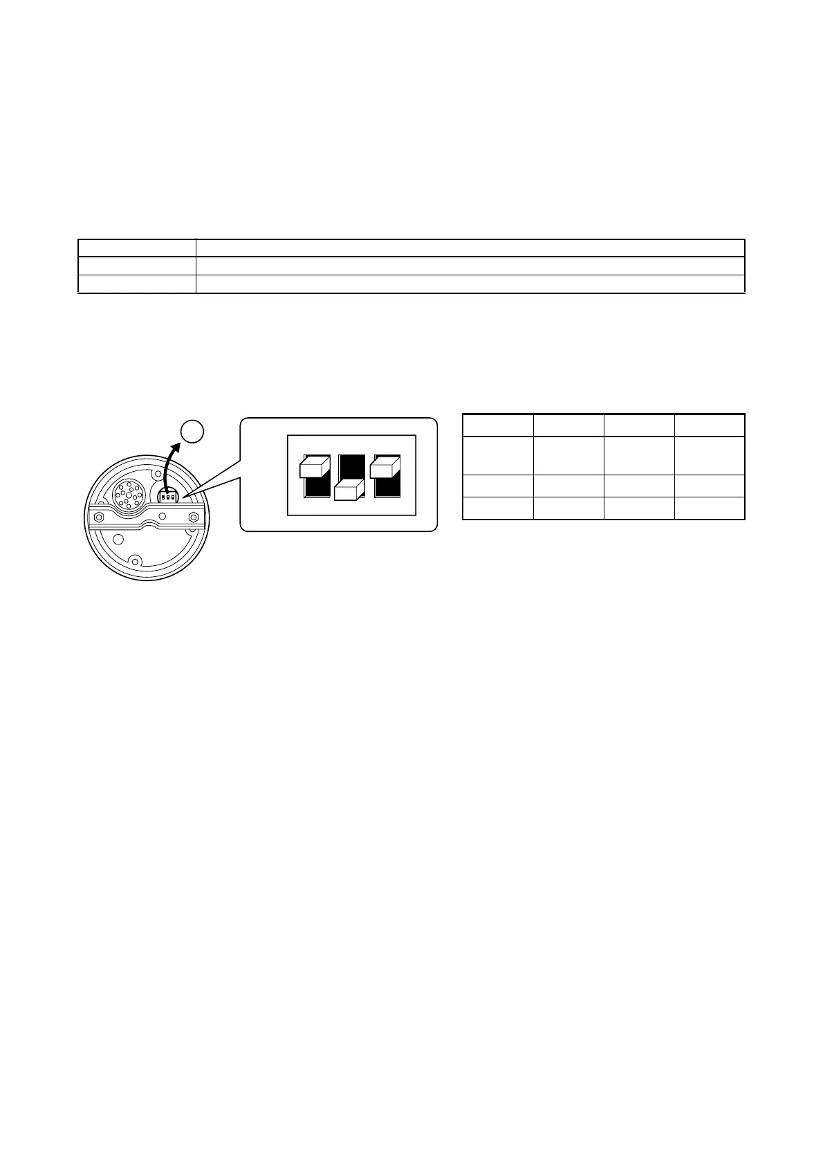
POLE NUMBER ADJUSTMENT
1. Remove the rubber grommet from the back the meter.
2. Set the toggle dipswitches on the chart as shown.
3. Reinstall the grommet.
* The switch position in the illustration shows the initial setting.
Description Applicable model
6-pole 40V, 50H (50), 40Y, 60F, 70B (70)
12-pole 75C, 90A (90), V4, V6, FT25B (T25), F30 – F250 [6P2]
No. SW.1SW.2SW.3
Dipswitch
function
Trim sen-
sor type
Genera-
tor type
Engine
type
ON 2 lead 6-pole 4-stroke
OFF 3 lead 12-pole 2-stroke
ON
OFF
SW.1 SW.2 SW.3
 Loading...