65
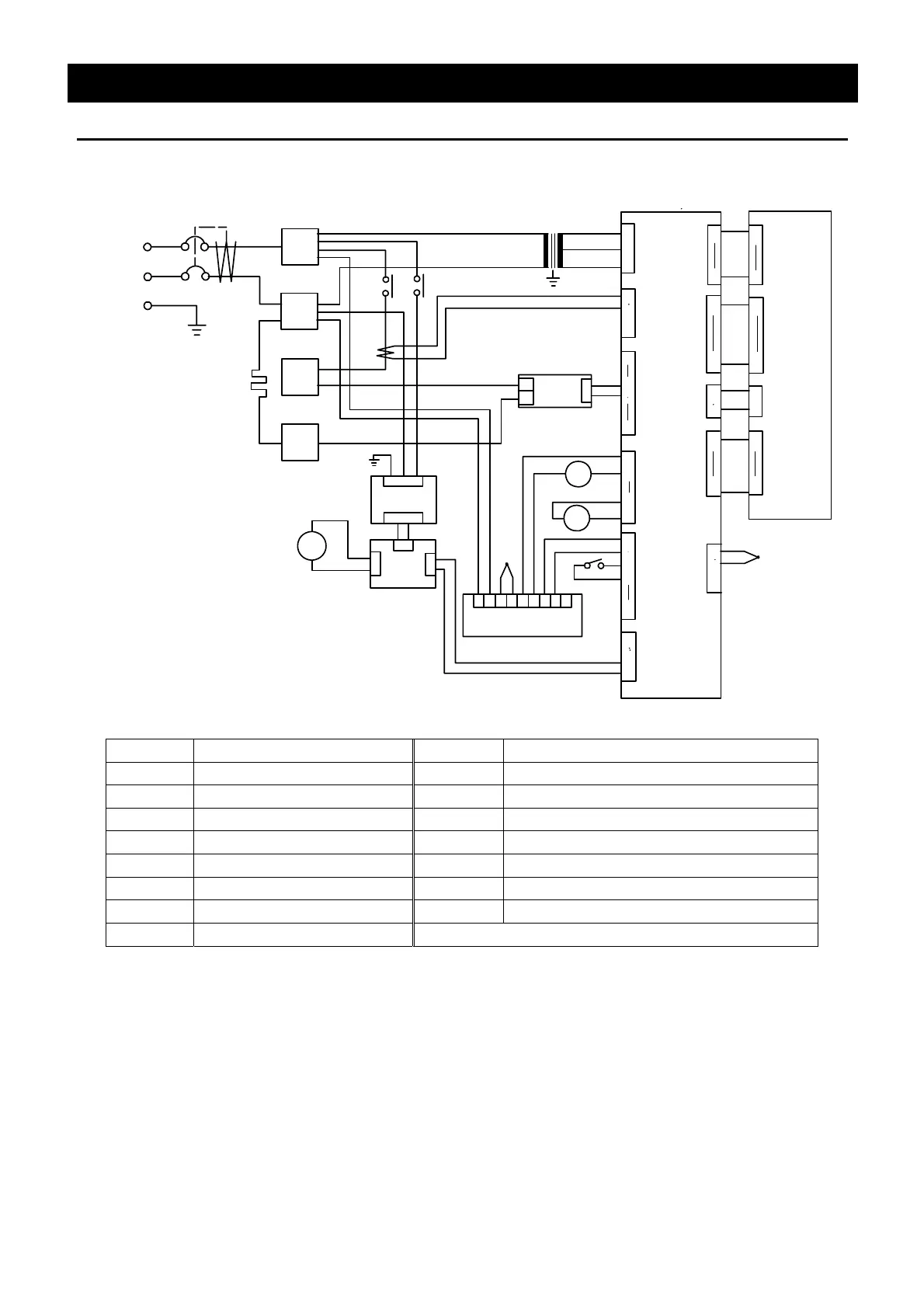
Wiring Diagram
DNF400/600
1
1
3
SSR
T1
T2
TF
TM
ELB
H
FM
X1
X2
X1
2
3
4
J
1
CT
AC100V
7
+
-
6
OH
①
②
③
④
⑪
1
2
CONT
1
30
CN1
PIO
1
30
1
3
5
J1
1
2
J8
8
7
J7
J5
3
4
6
5
2
1
1
11
J22
J19
J21
2
1
J2
12
CN4
CN5
1
12
1
12
2
1
1
TH1
1
10
J18
CN2
1
10
34
2
1
12
J10
3
4
2
1
+
-
TH2
⑧
⑩
⑫
⑬
5
98
3
4
DS
12
CN4
1
2
CN3
2
1
CN2
43
LFG
CN1
N
DC
RA
X2
1
2
CN1
⑦
⑰
⑱
⑨
3
4
2
1
J3
Symbol Part name Symbol Part name
ELB Earth leakage breaker SSR Triac
FM Fan motor OH Independent overheating prevention device
H Heater CT Current transformer
TM Terminal block TH1/TH2 Temperature sensor (K thermocouple)
TF Transformer CONT PLANAR board
X1 Relay (heater) PIO Display circuit board
X2 Relay (fan) DC/RA Fan controller
DS Door switch
 Loading...