7.2 List of User Constants
Constant No. Name Size Units
Range Factory Settings
Cn-0001 Memory switches 1 2 bit
— 0380H
Cn-0002 Memory switches 2 2 bit
—
0000H
Cn-0003
Load inertia 2 %
0 to 65535 100
Cn-0004
Speed loop gain 2 0.1 Hz
1 to 20000 400
Cn-0005
Speed loop integration
time constant
2 0.01 ms
100 to 65535 2000
Cn-0006 Emergency stop torque 2
% 0 to MAX
MAX
Cn-0007 Positioning near detection
width
2
Reference units
0 to 10000
10
Cn-0008
Forward torque limit 2
% 0 to MAX
MAX
Cn-0009
Reverse torque limit 2 %
0 to MAX
MAX
Cn-000A
Reserved for system
2 —
— 0000H
Cn-000B
Reserved for system
2 —
—
0000H
Cn-000C
Torque reference mode
switch level
2 %
0 to 32767
200
Cn-000D
Reserved for system
2 —
—
0000H
Cn-000E
Acceleration mode switch
level
2 0.167 r/s2
0 to 3000
0
Cn-000F Error pulses mode switch
level
2 Pulse
0 to 10000
0
Cn-0010 Reserved for system
2 —
—
0000H
Cn-0011 Number of encoder pulses 2 P/R
513 to 32767
Capacity
Cn-0012 Time delay from brake ref-
erence to Servo OFF
2
10 ms
0 to 50
0
Cn-0013
Memory switches 3 2 bit
0000H
Cn-0014
Memory switches 4 2
bit
—
0000H
Cn-0015
Brake timing during motor
running (reference output
speed)
2
r/min
0 to MAX 100
7.2 List of User Constants
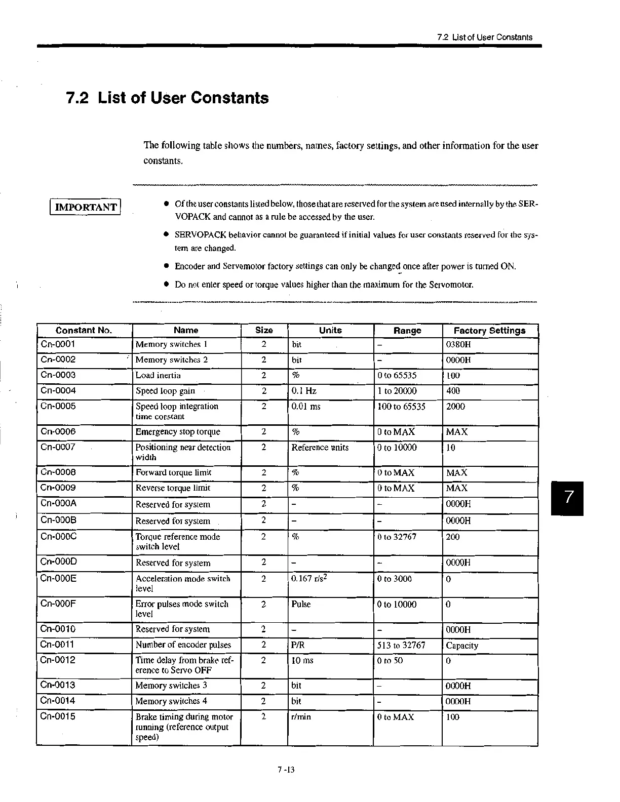
The following table shows the numbers, names, factory settings, and other information for the user
constants.
IMPORTANT
• Of the user constants listed below, those that are reserved for the system are used internally by the SER-
VOPACK and cannot as a rule be accessed by the user.
• SERVOPACK behavior cannot be guaranteed if initial values for user constants reserved for the sys-
tem are changed.
• Encoder and Servomotor factory settings can only be changed once after power is turned ON.
• Do not enter speed or torque values higher than the maximum for the Servomotor.
7 -13
 Loading...


