4.2 Name and Description of Main Circuit Terminals
Terminal Signal
Name
Description
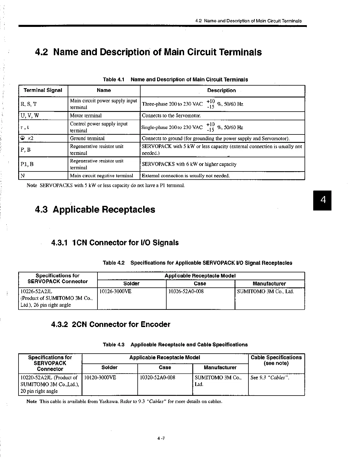
R, S, T
Main circuit power supply input
terminal
+10
Three-phase 200 to 230 VAC %, 50/60 Hz
-15
U, V, W
Motor terminal Connects to the Servomotor.
r , t
Control power supply input
terminal
+10
Single-phase 200 to 230 VAC %, 50/60 Hz
-15
(j) x2
Ground terminal Connects to ground (for grounding the power supply and Servomotor).
P B,
Regenerative resistor unit
terminal
SERVOPACK with 5 kW or less capacity (external connection is usually not
needed.)
P1, B
Regenerative resistor unit
terminal
SERVOPACKS with 6 kW or higher capacity
N
Main circuit negative terminal External connection is usually not needed.
Specifications for
SERVOPACK Connector
Applicable Receptacle Model
Solder Case
Manufacturer
10226-52A2JL
(Product of SUMITOMO 3M Co.,
Ltd.), 26 pin right angle
10126-3000VE 10326-52A0-008
SUMITOMO 3M Co., Ltd.
Specifications for
SERVOPACK
Connector
Applicable Receptacle Model Cable Specifications
(see note)
Solder
Case Manufacturer
10220-52A2JL (Product of
SUMITOMO 3M Co.,Ltd.),
20 pin right angle
10120-3000VE
10320-52A0-008
SUMITOMO 3M Co.,
Ltd.
See 9.3 "Cables".
4.2 Name and Description of Main Circuit Terminals
Table 4.1 Name and Description of Main Circuit Terminals
Note SERVOPACKS with 5 kW or less capacity do not have a P1 terminal.
4.3 Applicable Receptacles
4.3.1 1CN Connector for I/O Signals
Table 4.2 Specifications for Applicable SERVOPACK I/O Signal Receptacles
4.3.2 2CN Connector for Encoder
Table 4.3 Applicable Receptacle and Cable Specifications
Note This cable is available from Yaskawa. Refer to 9.3 "Cables" for more de ails on cables.
4 -7
 Loading...


