Servod rive Characteristics
Tolerance (T.I.R.) Reference Diagram
Perpendicularity between the flange 0,04 mm
face and output shaft 0 (0.0016 in)
INlit
Mating concentricity of flange O.D. 0.04 mm
0 (0.0016 in)
Run-out at the end of the shaft 0.02 mm
O(0.0008 in)
0.04 mm
(0.0016 in)
3.5.5 Impact Resistance
Note Radial and thrust load limit value are the sum of the loads generated by the motor
torque and external loads applied to the shaft.
3.5.3 Mechanical Tolerances
To le ra nc es for AC Servomotor output shaft and installation are shown in Table 3.2.
Table 3.2 Mechanical Tolerances
Note T.I.R. = Total Indicator Reading
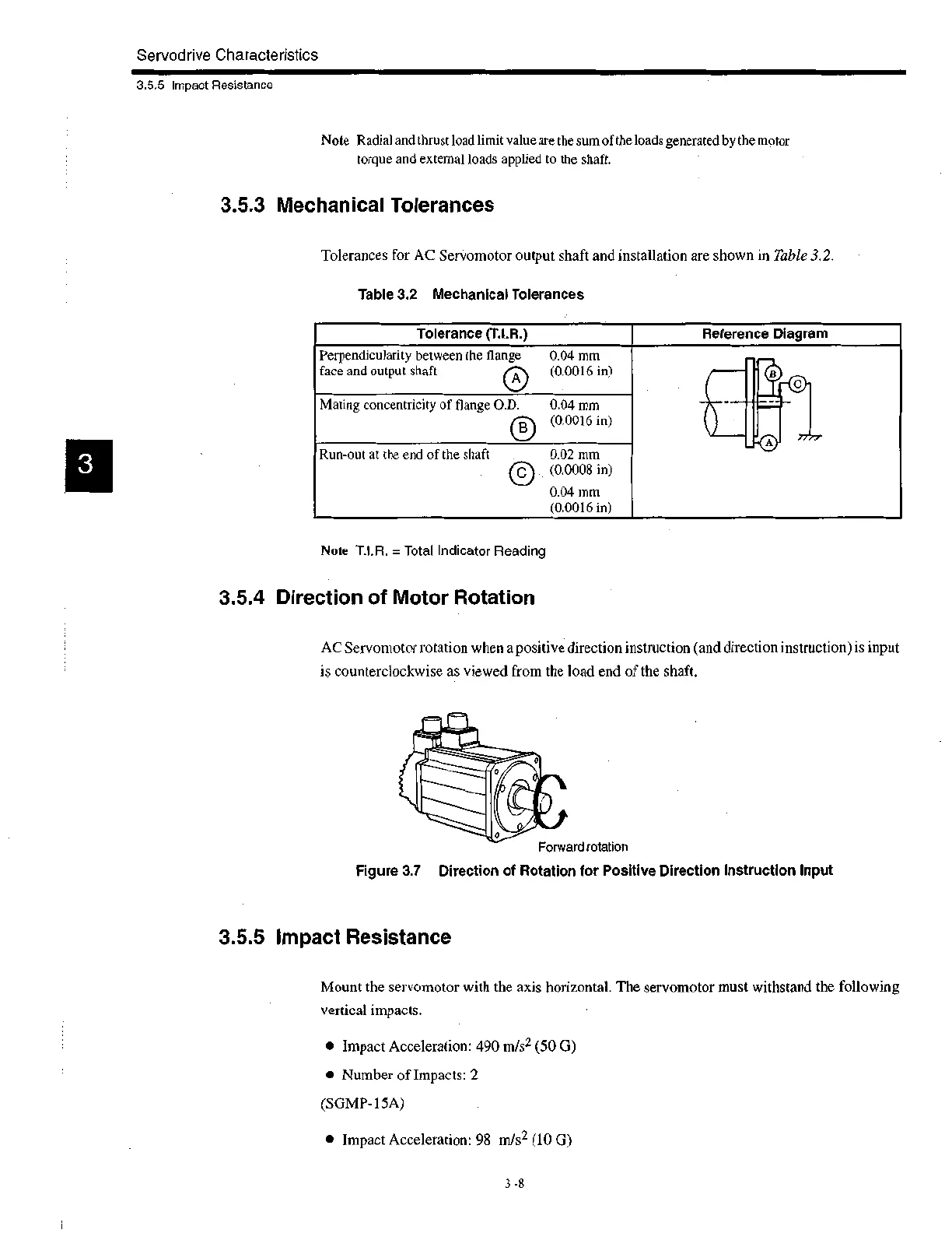
3.5.4 Direction of Motor Rotation
AC Servomotor rotation when a positive direction instruction (and direction instruction) is input
is counterclockwise as viewed from the load end of the shaft.
Forward rotation
Figure 3.7 Direction of Rotation for Positive Direction Instruction Input
3.5.5 Impact Resistance
Mount the servomotor with the axis horizontal. The servomotor must withstand the following
vertical impacts.
• Impact Acceleration: 490 m/s2 (50 G)
• Number of Impacts: 2
(SGMP-15A)
• Impact Acceleration: 98 m/s2 (10 G)
3 -8
 Loading...


