102777-YIM-E-0206
Unitary Products Group 15
POWER AND CONTROL WIRING
Field wiring to the unit must conform to provisions of National
Electrical Code (NEC) ANSI / NFPA 70-Latest Edition and / or
local ordinances. The unit must be electrically grounded in
accordance with the NEC and / or local codes. Voltage toler-
ances which must be maintained at the compressor terminals
during starting and running conditions are indicated on the
unit Rating Plate and Table 1.
The internal wiring harnesses furnished with this unit are an
integral part of the design certified unit. Field alteration to
comply with electrical codes should not be required. If any of
the wire supplied with the unit must be replaced, replacement
wire must be of the type shown on the wiring diagram and the
same minimum gauge as the replaced wire.
Power supply to the unit must be NEC Class 1 and must
comply with all applicable codes. A disconnect switch must
be provided (factory option available). The switch must be
separate from all other circuits. Wire entry at knockout open-
ings requires conduit fittings to comply with NEC and/or Local
Codes. Refer to Figures 13, 14, 15, and 16 for installation
location of openings.
If installing a field mounted disconnect on the unit, refer to
Figure 17 for the recommended mounting location. Unit-
strutTM or equivalent rails should be mounted as shown to
provide structure for mounting. The location of the rails
should be adjusted to fit the disconnect within the dimensions
shown. Conduit run from the disconnect to the power entry
location in the baserail should be routed so that it does not
interfere with the doors of the unit access panels.
NOTE: Since not all local codes allow the mounting of a dis-
connect on the unit, please confirm compliance with
local code before mounting a disconnect on the unit.
Electrical wiring must be sized properly to carry the load.
Each unit must be wired with a separate branch circuit fed
directly from the meter panel and properly fused.
Refer to Figure 5 for typical field wiring and to the appropriate
unit wiring diagram mounted inside control doors for control
circuit and power wiring information.
POWER WIRING DETAIL
Units are factory wired for the voltage shown on the unit
nameplate. The main power block requires copper wires.
Refer to Electrical Data Tables 13 through 24 to size power
wiring, fuses and disconnect switch. All field supplied wiring,
fuses and disconnects must comply with applicable NEC
codes.
Power wiring is brought into the unit through the side of the
baserail or the bottom of the unit/control box inside the curb.
The baserail has a 2-1/2” diameter hole for field wiring and a
3-5/8” hole is provided for a through-the-curb connection. A
removable patch plate covers both the openings.
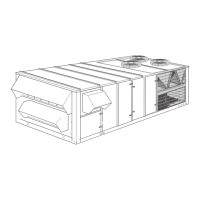
ERV
The ERV [Energy Recovery Ventilation] is a separate air han-
dler that attaches to the exhaust end of the 25-40T Millen-
nium packaged rooftop unit. The ERV is shipped separately
and assembled to the Millennium at the jobsite. An 'ERV' Mil-
lennium is shipped with an end configuration and electric
hookups designed to mate with the ERV. This option is avail-
able only with the Simplicity control, and no other power
exhaust option can be supplied if an ERV is selected.
The ERV incorporates a rotating heat exchange wheel and a
pair of exhaust blowers. It exhausts return air through the
wheel, capturing the thermal energy of the exiting hot or cold
air as it passes. As the wheel rotates, the incoming airstream,
pulled through by the supply fan, regains that energy.
The Millennium ERV has a terminal block and mating con-
nectors to simplify hooking up the two systems. The controls
of both units are factory set to interact properly. Power for the
ERV blower motors and controls is provided through the Mil-
lennium unit. The Millennium /ERV dataplate information
includes the ERV electrical load.
The Millennium Simplicity control has parameters for the
ERV; ref. the parameter list. When economizer and ERV
options are selected on the same unit, the Simplicity control
and the ERV have specific connections and internal rules for
that operation.
Also refer to the ERV Installation Instructions packaged with
the ERV.
Use care to avoid damage when drilling holes for
the disconnect mounting.
When connecting electrical power and control wir-
ing to the unit, waterproof connectors MUST BE
USED so that water or moisture cannot be drawn
into the unit during normal operation. The above
waterproofing conditions will also apply when
installing a field-supplied disconnect switch.
Waterproof connections MUST be used to ensure
that water cannot penetrate the roof or roof curb.
 Loading...