102777-YIM-E-0206
18 Unitary Products Group
3. Place the flue extension (Figure 9) on the flue duct of
each furnace section and attach with screws provided.
4. Place the flue in position with the diverter angles facing
up toward the top of the unit and attach with screws pro-
vided.
5. Place the wind shield over the louvers on the right side of
the burner access door and attach with screws provided.
6. Refer to the Gas Furnace Operation Instructions in the
Start-up Section of this manual for further information.
ELECTRIC HEAT
Units with electric heat are fully wired and operational when
shipped. Constant volume units are designed for two equal
steps of capacity for 80 and 108 kWH heat; 40 kW heat is one
step only. VAV units are one full step at full heat capacity.
HOT WATER HEAT
The YORK Millennium units (25, 30, and 40 Ton sizes) can be
furnished with a YORK hot water coil as the heat source. One
or two row coil units will be factory installed in the heating
section.
NOTE: The hot water control valve will not be provided. The
installer will need to purchase a hot water control
valve, to connect the hot water piping and power
wiring at the job site for the hot water heat section to
be operational.
NOTE: For all hot water coils the entering water tempera-
ture should not exceed 200°F.
The hot water coil is located downstream of the supply air fan
and just above the supply air opening in the bottom of the
unit.
Refer to Tables 58 through 66 and Figures 36 through 49 for
flow rate and capacity.
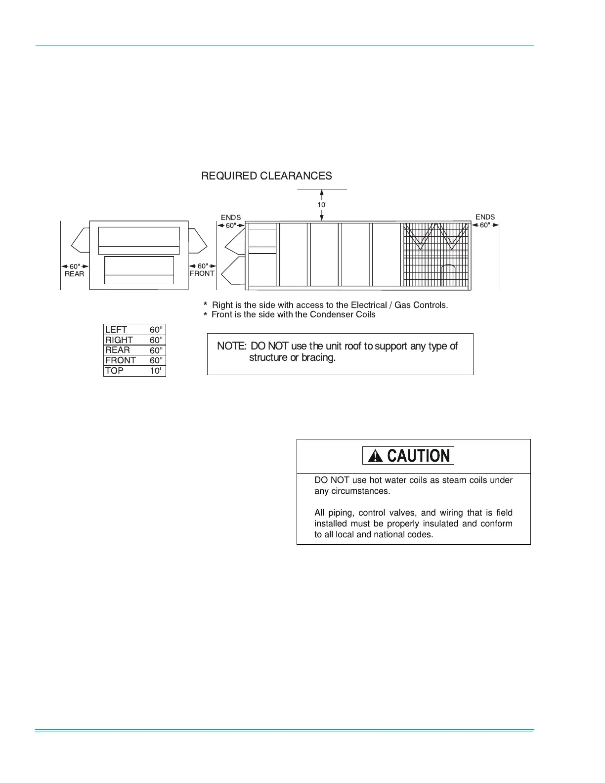
FIGURE 10 - CLEARANCES
60"
REAR
60"
FRONT
60"
ENDS
10'
60"
ENDS
REQUIRED CLEARANCES
LEFT
RIGHT
REAR
FRONT
TOP
60"
60"
60"
60"
10'
* Right is the side with access to the Electrical / G as Controls.
*
is the side with the Condenser Coils
NOT E: D O NO T u se th e unit r oof to support a ny type of
structure or b racing.
Front
DO NOT use hot water coils as steam coils under
any circumstances.
All piping, control valves, and wiring that is field
installed must be properly insulated and conform
to all local and national codes.
 Loading...