JOHNSON CONTROLS
100
Form 150.63-NM9
Issue date: 5/20/2021
SECTION 5 – TECHNICAL DATA
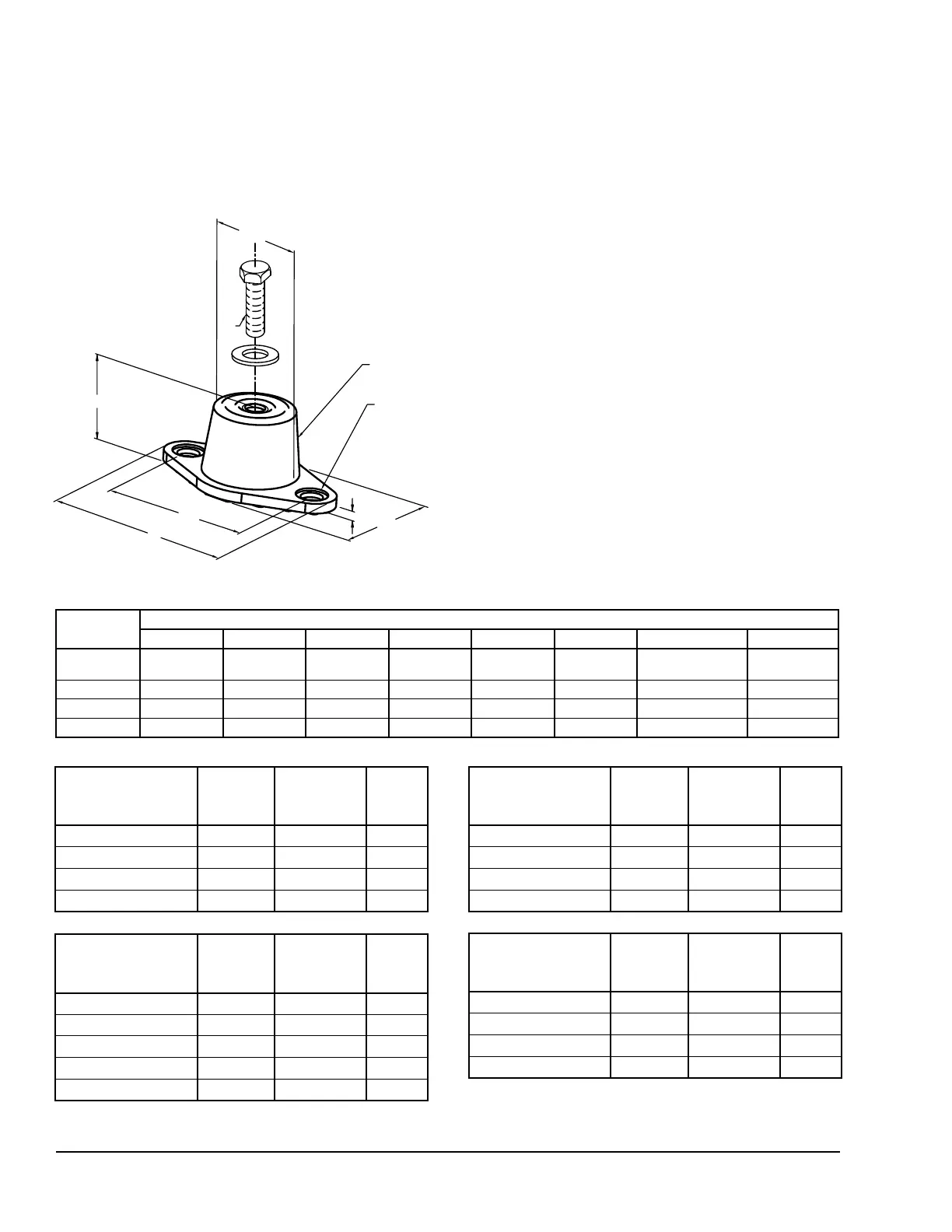
RD-Style
Isolators
Durulene isolator cross-reference
L
AL
DW
BT
HF
ø AD THRU
TYP 2 PLACES
MOLDED
DURULENE
CD
W
Notes:
1. All dimensions are inches, interpreted per ANSI Y14.
2. Refer to next page for installation instructions.
3. Mount molded in weather resistant duralene compound as standard. Also available in other materials
such as natural rubber, extreme high temperature silicone, high-damped silicone, nitrile and EDPM.
4. AL = Mounting hole center to center spacing.
5. HF = Free height of mount, prior to loading. Operating height calculated by the free height less the
static deflection under load. All dimensions for reference only.
6. Hardware zinc-electroplated.
MOUNT
TYPE
DIMENSION DATA (in.)
L W HF AL AD BT CD DW
RD1-WR 3.13 1.75 1.25 2.38 0.34 0.19 5/16-18 UNC X 3/4 1.25
RD2-WR 3.88 2.38 1.75 3.00 0.34 0.22 3/8-16 UNC X 1 1.75
RD3-WR 5.50 3.38 2.88 4.13 0.56 0.25 1/2-13 UNC X 1 2.50
RD4-WR 6.25 4.63 2.75 5.00 0.56 0.38 1/2-13 UNC X 1 3.00
MODEL NUMBER
RATED
CAPACITY
[LB]
RATED
DEFLECTION
[IN.]
DURO
(± 5)
RD2-Light Blue-WR 35 0.4 30
RD2-Brown-WR 45 0.4 40
RD2-Brick Red-WR 70 0.4 50
RD 2-Lime-WR 120 0.4 60
MODEL NUMBER
RATED
CAPACITY
[LB]
RATED
DEFLECTION
[IN.]
DURO
(± 5)
RD2-Light Blue-WR 135 0.5 30
RD2-Brown-WR 170 0.5 40
RD2-Brick Red-WR 240 0.5 50
RD 2-Lime-WR 380 0.5 60
RD2 Charcoal-WR 550 0.5 70
MODEL NUMBER
RATED
CAPACITY
[LB]
RATED
DEFLECTION
[IN.]
DURO
(± 5)
RD3-Brown-WR 250 0.5 40
RD3-Brick Red-WR 525 0.5 50
RD3-Lime-WR 750 0.5 60
RD3-Charcoal-WR 1100 0.5 70
MODEL NUMBER
RATED
CAPACITY
[LB]
RATED
DEFLECTION
[IN.]
DURO
(± 5)
RD4-Brown-WR 1500 0.5 40
RD4-Brick Red-WR 2250 0.5 50
RD4-Lime-WR 3000 0.5 60
RD4-Charcoal-WR 4000 0.5 70
Figure 38 - Durulene Isolator Cross-Reference
Notes:
1. All dimensions are inches, interpreted beforeANSI Y14.
2. See next page for installation instructions.
3. Mount molded in weather resistant duralene compound as
standard. Also available in other materials such as natural rubber,
extreme high temperature silicone, high-damped silicone, nitrile
and EDPM.
4. AL = Mounting hole center to center spacing.
5. HF = Free height of mount, before loading. Operating height
calculated by the free height less the static deection under load.
All dimensions for reference only.
6. Hardware is zinc-electroplated.
 Loading...