JOHNSON CONTROLS
140
Form 150.63-NM9
Issue date: 5/20/2021
SECTION 8 – UNIT OPERATION
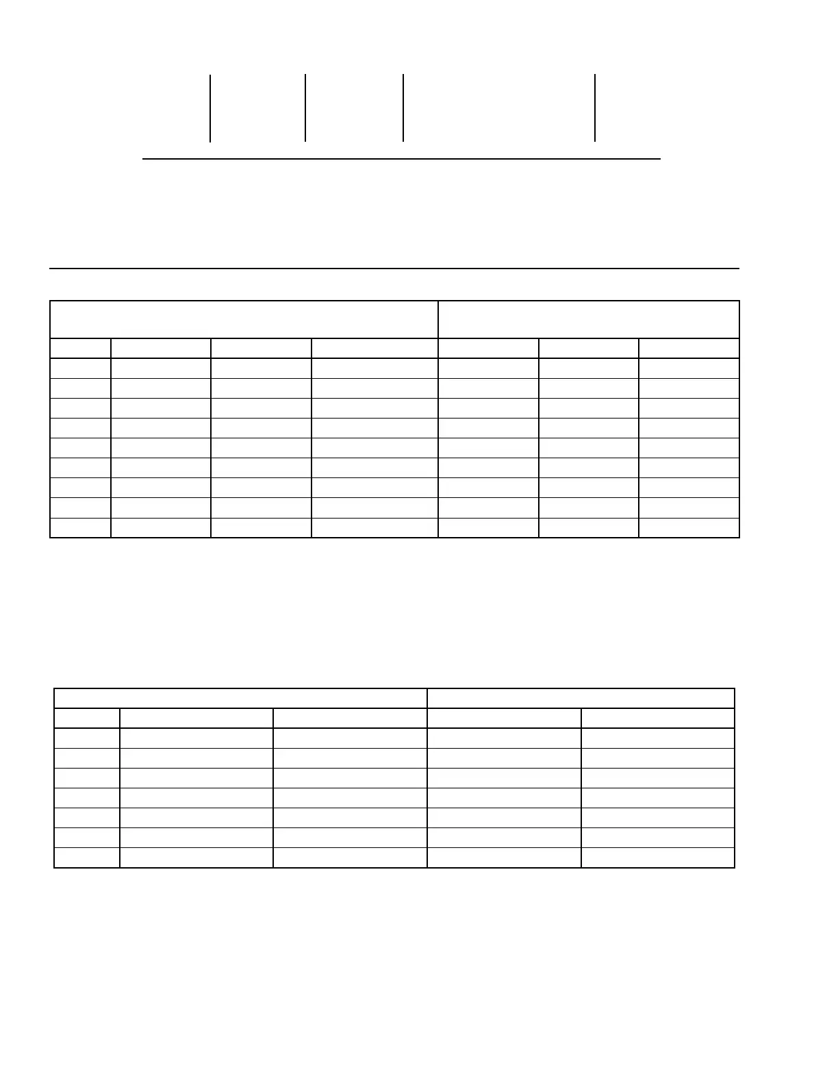
Figure 40 - Discharge Air Temperature Control
20 sec. 30 sec. 60 sec. control range 60 sec.
unloading unloading unloading (no compressor staging) loading
51.5°F 52.5°F 53.0°F 55.0°F 57.0°
(10.8°C) (11.4°C) (11.7°C) (12.8°C) (13.9°C)
Low Limit Setpoint High limit
Discharge Air Temperature Control – Compressor Staging
Setpoint = 55.0°F (12.8°C) Range = +/- 5°F (-12.2°C)
Table 17 - Discharge Air Temperature Control for 5 and 6 Compressors (7 and 8 Steps)
LEAD SYSTEM LAG SYSTEM
*STEP COMP 1 COMP 2 COMP 3 COMP 1 COMP 2 COMP 3
0 OFF OFF OFF OFF OFF OFF
1 ON+HG OFF OFF (See Note 1) OFF OFF OFF
2 ON OFF OFF OFF OFF OFF
3 ON OFF OFF (See Note 2) ON OFF OFF
4 ON ON OFF (See Note 3) OFF OFF OFF
5 ON ON OFF ON OFF OFF
6 ON ON OFF ON ON OFF
7 ON ON ON ON ON OFF
8 ON ON ON ON ON ON
Notes:
1. Step 1 is Hot Gas Bypass and is skipped when loading occurs. Hot Gas Bypass operation is inhibited during Pumpdown. For Discharge Air
Temperature Control the Hot Gas Bypass solenoid is energized only when the lead compressor is running and the DAT is less than SP, the
Hot Gas Bypass solenoid is turned OFF when the DAT is more than SP + CR/2.
2. Step 3 is skipped when loading occurs.
3. Step 4 is skipped when unloading occurs.
* STEP can be viewed using the OBeforeDATA key and scrolling to COOLING DEMAND.
Table 18 - Discharge Air Temperature Control for 4 Compressors (6 Steps)
* STEP can be viewed using the OBeforeDATA key and scrolling to COOLING DEMAND.
Notes:
1. Step 1 is Hot Gas Bypass and is skipped when loading occurs. Hot Gas Bypass operation is inhibited during Pumpdown. For Discharge Air
Temperature Control the Hot Gas Bypass solenoid is energized only when the lead compressor is running and the DAT is less than SP, the
Hot Gas Bypass solenoid is turned OFF when the DAT is more than SP + CR/2.
2. Step 3 is skipped when loading occurs.
3. Step 4 is skipped when unloading occurs.
* STEP can be viewed using the OBeforeDATA key and scrolling to COOLING DEMAND.
LEAD SYSTEM LAG SYSTEM
*STEP COMP 1 COMP 2 COMP 1 COMP 2
0 OFF OFF OFF OFF
1 ON+HG OFF (See Note 1) OFF OFF
2 ON OFF OFF OFF
3 ON OFF (See Note 2) ON OFF
4 ON ON (See Note 3) OFF OFF
5 ON ON ON OFF
6 ON ON ON ON
 Loading...