JOHNSON CONTROLS
33
SECTION 4 – INSTALLATION
Form 150.63-NM9
Issue date: 5/20/2021
4
System Run Contacts
Contacts are available to monitor system status. Normal-
ly-open auxiliary contacts from each compressor contac-
tor are wired in parallel with TB1 – Terminals 25 to 26 for
system 1, and TB1 – Terminals 27 to 28 for system 2. See
Figure 4 on page 22, Figure 11 on page 39, and the
unit wiring diagrams starting on page 52.
Alarm Status Contacts
Normally-open contacts are available for each refriger-
ant system. These normally-open contacts close when
the system is functioning normally. The respective
contacts will open when the unit is shut down on a unit
fault, or locked out on a system fault. Field connections
are at TB1 - Terminals 29 to 30 (system 1), and Termi-
nals 31 to 32 (system 2).
Remote Start/Stop Contacts
To remotely start or stop a single circuit unit, wire a
dry contact in series with the flow switch and then con-
nect it to terminals 13 to 51 of CTB1. See Figure 4 on
page 22, Figure 11 on page 39, and the unit wiring
diagrams starting on page 52.
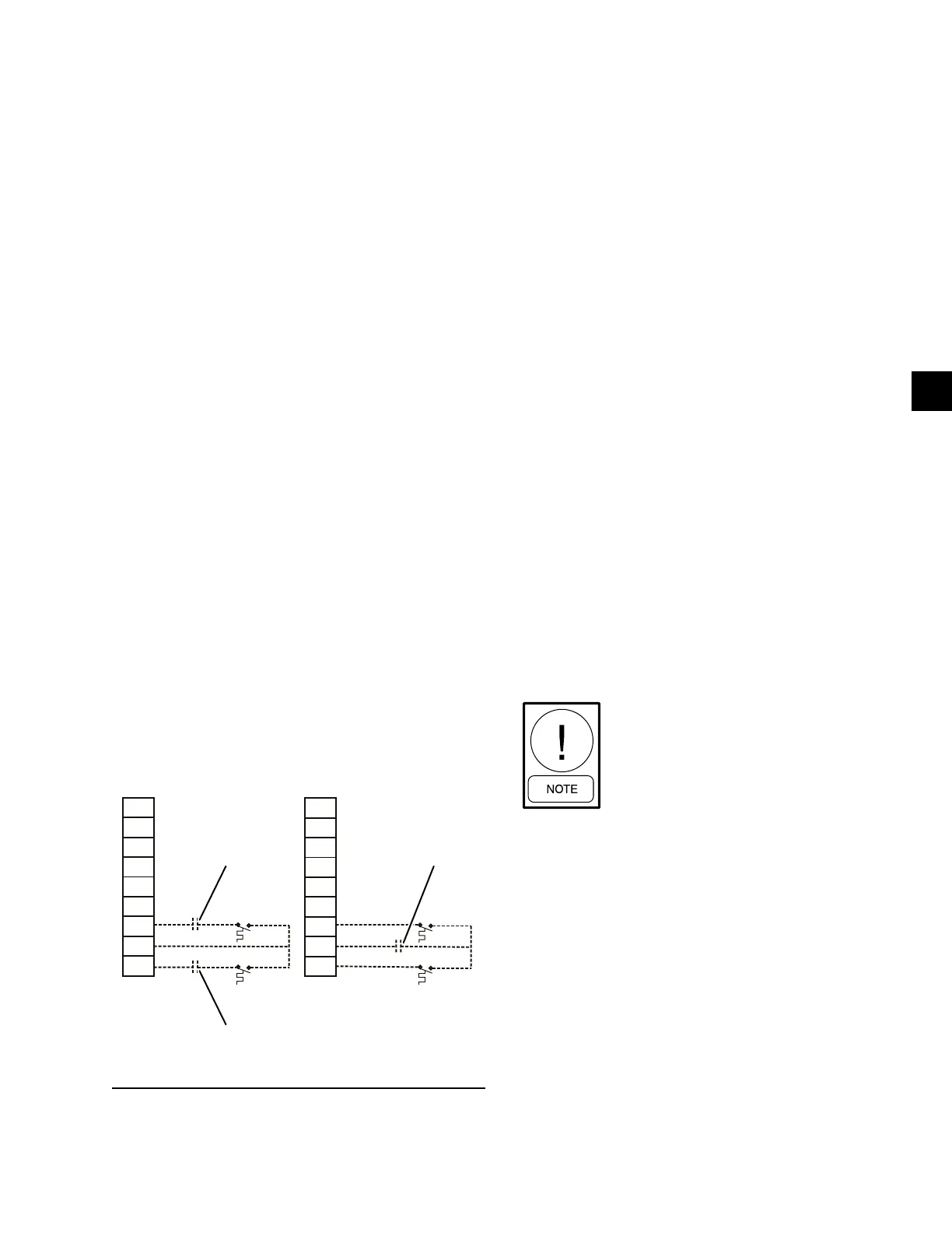
To remotely start or stop a dual system unit, individu-
ally wire two dry contacts in series with the correspon-
dent thermostat, then respectively connect them to ter-
minals 13 to 51 (System #1) and 13 to 50 (System #2)
of CTB1, as shown left on Figure 8. The other option is
to wire only one dry contact to the common wire con-
nected to terminal 13 of CTB1, as shown on the right
on Figure 8. See Figure 4 on page 22, Figure 11 on
page 39, and the unit wiring diagrams starting on page
52.
Figure 8 - Wiring Options for Remotely Start or Stop
the Dual System Unit
LD28300
13
20
13
13
21
14
51
13
50
CBT1
Dry Contact of System #1
Dry Contact of System #2
13
13
20
21
14
13
51
13
50
CBT1
Single Dry Contact
Remote Emergency Cutoff
Immediate shutdown of the chiller can be accomplished
by opening a field-installed dry contact to break the
electrical circuit between Terminals 5 to L on Terminal
Block TB1. The unit is shipped with a factory jumbe-
foreinstalled between Terminals 5 to L, which must be
removed if emergency shutdown contacts are installed.
See Figure 11 on page 39 and the unit wiring diagrams
starting on page 52.
Remote Temp Reset Input
The Remote Temp Reset input allows reset of the dis-
charge air temperature setpoint by supplying a voltage
or current signal field wiring should be connected to
CTB1 – Terminals A+ to A-. A detailed explanation is
provided in the Unit Control section. See Figure 3 on
page 21, Figure 4 on page 22, and the unit wiring
diagrams starting on page 52.
Load Limit Input
Load limiting is a feature that prevents the unit from
loading beyond a desired value. The unit can be “load
limited” either 33%, 40%, 50%, 66% or 80%, depend-
ing on the number of compressors on unit. The field
connections are wired to CTB1 – Terminals 13 to 21,
and work in conjunction with the PWM inputs. A de-
tailed explanation is provided in the Unit Control sec-
tion. See Figure 4 on page 22, Figure 11 on page 39
and the unit wiring diagrams starting on page 52.
When using the Load Limit feature, the
PWM feature will not function – SIMUL-
TANEOUS OPERATION OF LOAD
LIMITING AND TEMPERATURE
RESET (PWM INPUT) CANNOT BE
DONE.
Liquid Line Solenoid Connections
The field supplied and installed liquid line solenoid
valves should be installed at the evaporator and wired
using 18 AWG minimum wire. Electrical connections
should be made at Terminal Board TB1. TB1 is located
in the power panel on the left side of the power panel.
Note that power for the solenoid coil is 120 VAC.
See Figure 11 on page 39 and the unit wiring diagrams
starting on page 52.
 Loading...