JOHNSON CONTROLS
39
SECTION 4 – INSTALLATION
Form 150.63-NM9
Issue date: 5/20/2021
4
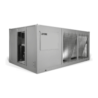
Figure 11 - Control Wiring
* Factory wired with optional transformer.
LD28296
POWER SUPPLY* 120V-1PH-60Hz L TO 2
EVAP BLOWER STAR CONTACTS
REMOTE EMERGENCY CUTOFF
(MUST BE CLOSED TO OPERATE)
CHILLER RUN STATUS SYSTEM 1
CHILLER RUN STATUS SYSTEM 2
SYS # 1 ALARM STATUS
SYS # 2 ALARM STATUS (ON 2ND CIRCUIT ONLY)
TB1
2
L
5
23
24
GRD
GRD
GRD
25
26
27
28
29
30
31
32
GRD
It is possible that multiple sources of
power can be supplying the unit power
panel. To prevent serious injury or death,
the technician should verify that NO
LETHAL VOLTAGES are present inside
the panel AFTER disconnecting power,
before working on equipment.
The unit evaporator heater uses 120 VAC.
Disconnecting 120 VAC power from the
unit, at or below freezing temperatures,
can result in damage to the evaporator
and unit as a result of the chilled liquid
freezing.
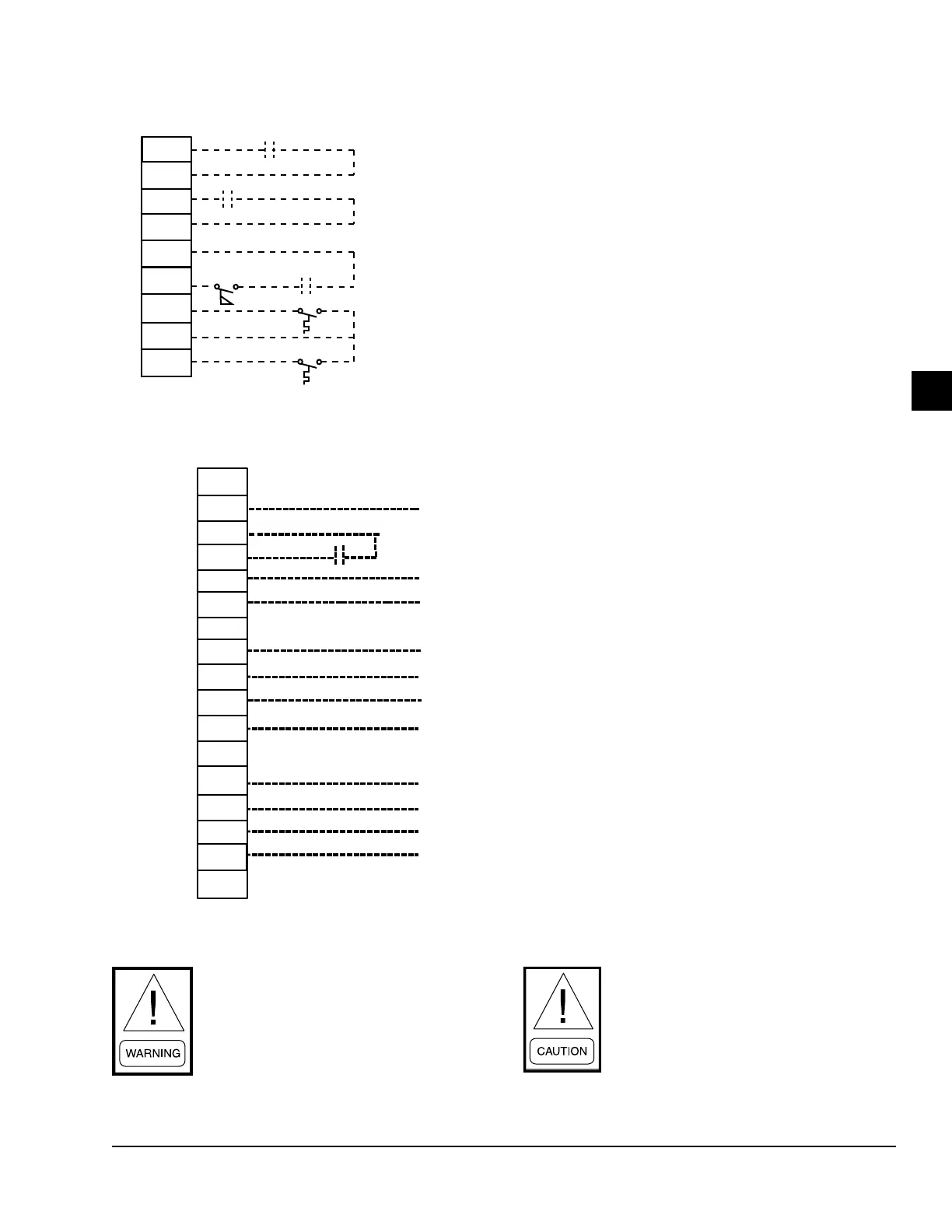
Control wiring
CTB1
51
13
14
13
50
SYSTEM 2 THERMOSTAT (SUCTION PRESSURE CONTROL ONLY)
SYSTEM 1 THERMOSTAT (SUCTION PRESSURE CONTROL ONLY)
AIR FLOW SWITCH AND REMOTE START/STOP
21
13
20
13
PWM INPUT (CAN ONLY BE USED WITH DISCHARGE AIR
TEMP CONTROL)
LOAD LIMIT INPUT
 Loading...