JOHNSON CONTROLS
62
Form 150.63-NM9
Issue date: 5/20/2021
SECTION 5 – TECHNICAL DATA
YCUL0045-YCUL0072 Low sound
YCUL0045-0072 Ultra low sound
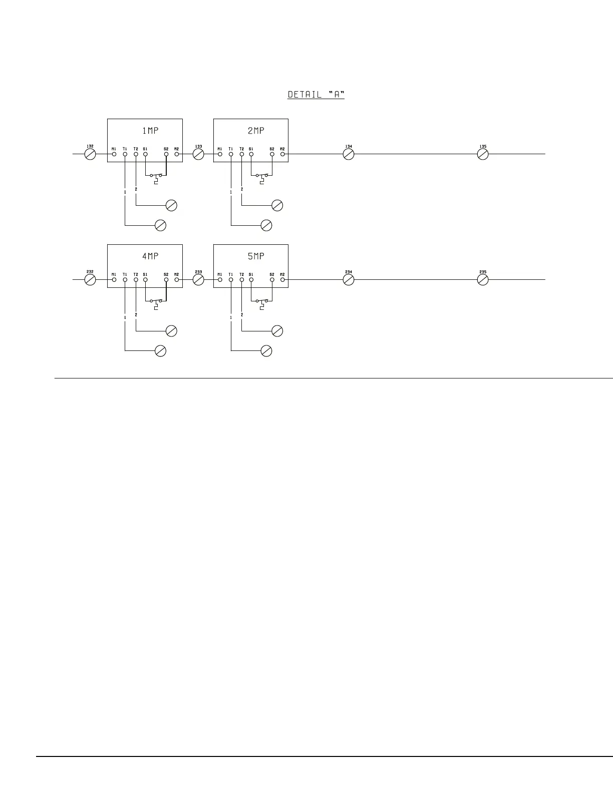
Figure 17 - Control Wiring Diagram, Details, Dual Circuit
035-20880-103 REV C
Notes:
1. Field wiring to be in accordance with the current edition of the National Electrical Code as well as all other applicable codes and speci-
cations.
2. Contacts must be suitable for switching 24 VDC, (gold contacts recommended). Wiring must not be run in the same conduit with any
line voltage (class 1) wiring.
3. To cycle unit on and o automatically with contact shown, install a cycling device in series with the ow switch. See note 2 for contact
rating and wiring specications.
4. To stop unit (emergency stop) with contacts other than those shown, install the stop contact between terminals 5 and 1. If a stop device
is not installed, a jumbeforemust be connected between terminals 5 and 1. Device must have a minimum contact rating of 6 A at 115
VAC.
5. Contacts are rated at 115 V, 100 VA, resistive load only, and must be suppressed at load by user.
6. See installation, operation and maintenance manual when optional equipment is used.
7. Optional current readout. 5 V = 200 A.
8. 1MP thru 6MP are contained in their respective compressor junction boxes.
 Loading...