1061903-XIM-A-0713
Johnson Controls Unitary Products 23
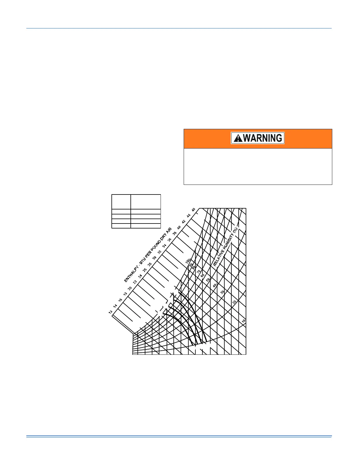
module) to the “A”, “B”, “C” or “D” setting corresponding
to the lettered curve of the Enthalpy Set Point
Adjustment Figure 20.
• For a dual enthalpy operation, carefully turn the set point
adjusting screw fully clockwise past the "D" setting.
Power Exhaust Damper Set Point
With power exhaust option, each building pressurization
requirement will be different. The point at which the power
exhaust comes on is determined by the economizer damper
position (Percent Open). The Exhaust Air Adjustment Screw
should be set at the Percent Open of the economizer damper at
which the power exhaust is needed. It can be set from 0 to
100% damper open.
Indoor Air Quality AQ
Indoor Air Quality (indoor sensor input): Terminal AQ accepts a
+2 to +10 Vdc signal with respect to the (AQ1) terminal. When
the signal is below it's set point, the actuator is allowed to
modulate normally in accordance with the enthalpy and mixed
air sensor inputs. When the AQ signal exceeds it's set point
setting and there is no call for free cooling, the actuator is
proportionately modulated from the 2 to 10 Vdc signal, with 2
Vdc corresponding to full closed and 10 Vdc corresponding to
full open. When there is no call for free cooling, the damper
position is limited by the IAQ Max damper position setting.
When the signal exceeds it's set point (Demand Control
Ventilation Set Point) setting and there is a call for free cooling,
the actuator modulates from the minimum position to the full
open position based on the highest call from either the mixed
air sensor input or the AQ voltage input.
• Optional CO
2
Space Sensor Kit Part # 2AQ04700324
• Optional CO
2
Sensor Kit Part # 2AQ04700424
Replace the top rear access panel on the unit.
Figure 19: Enthalpy Set Point Chart
Before beginning any service, disconnect all power to
the drive. Be aware that high voltages are present in the
drive even after power has been disconnected.
Capacitors within the drive must be allowed to discharge
before beginning service.
40
(4)
70
(21)
50
(10)
55
(13)
60
(16)
65
(18)
35
(2)
45
(7)
75
(24)
80
(27)
35
(2)
40
(4)
45
(7)
50
(10)
55
(13)
60
(16)
65
(18)
70
(21)
75
(24)
80
(27)
85
(29)
85
(29)
90
(32)
90
(32)
105
(41)
110
(43)
100
(38)
95
(35)
95
(35)
100
(38)
105
(41)
110
(43)
APPROXIMATE DRY BULB TEMPERATURE -
0
F (
0
C)
D
D
C
C
B
B
A
A
CONTROL
CURVE
CONTROL POINT
APPROX.
0
F (
0
C)
AT 50% RH
A
D
C
B
63 (17)
73 (23)
70 (21)
67 (19)
 Loading...