1061903-XIM-A-0713
36 Johnson Controls Unitary Products
controlled. On any fault, only the associated system will be
affected by any safety/preventive action. The other refrigerant
system will continue in operation unless it is affected by the
fault as well.
The unit control board monitors the temperature limit switch of
electric heat units and the temperature limit switch and the gas
valve of gas furnace units.
Compressor Protection
In addition to the external pressure switches, the compressors
also have inherent (internal) protection. If there is an abnormal
temperature rise in a compressor, the protector will open to shut
down the compressor. The UCB incorporates features to
minimize compressor wear and damage. An Anti-Short Cycle
Delay (ASCD) is utilized to prevent operation of a compressor
too soon after its previous run. Additionally, a minimum run time
is imposed any time a compressor is energized.
The ASCD is initiated on unit start-up and on any compressor
reset or lock-out.
Flash Codes
The UCB will initiate a flash code associated with errors within
the system. Refer to UNIT CONTROL BOARD FLASH CODES
Table 31.
Reset
Remove the call for cooling, by raising thermostat setting higher
than the conditioned space temperature. This resets any
pressure or freezestat flash codes.
Electric Heating Sequence Of Operations
The following sequence describes the operation of the electric
heat section.
Single-stage heating: (applies only to 18 KW heater, all other
heaters MUST use a two-stage thermostat)
a. Upon a call for heat by the thermostat, the heater
contactor (M6) will be energized. After completing the
specified fan on delay for heating, the UCB will energize
the blower motor.
b The thermostat will cycle the electric heat to satisfy the
heating requirements of the conditioned space.
Two-stage heating: (applies to all heaters except 18 KW)
a. Upon a call for first-stage heat by the thermostat, the
heater contactor (M6) will be energized. After completing
the specified fan on delay for heating, the UCB will
energize the blower motor.
If the second stage of heat is required, heater contactor
(M7) will be energized.
b The thermostat will cycle the electric heat to satisfy the
heating requirements of the conditioned space.
Electric Heat Operation Errors
Temperature Limit
If the UCB senses zero volts from the high temperature limit,
the indoor blower motor is immediately energized.
This limit is monitored regardless of unit operation status, i.e.
the limit is monitored at all times.
If the temperature limit opens three times within one hour, it will
lock-on the indoor blower motor and a flash code is initiated
(See Table 31).
Safety Controls
The UCB monitors the temperature limit switch of electric heat
units.
The control circuit includes the following safety controls:
Temperature Limit Switch (TLs)
1. Temperature Limit Switch (TLS 1, 2).
This control is located inside the heater compartment and
is set to open at the temperature indicated in the Limit
Control Setting Table 26. It resets automatically. The limit
switch operates when a high temperature condition,
caused by inadequate supply air flow occurs, thus shutting
down the heater and energizing the blower.
2. Temperature Limit Switch (TLS 3, 4, 5 and 6).
This control is located inside the heater compartment and
is set to open at the temperature indicated in the Limit
Control Setting Table 26. It is a manual reset limit. These
limit switches will de-energize the heaters should the
primary limit fail to open or the contactors fail to open in a
failure mode.
Flash Codes
The UCB will initiate a flash code associated with errors within
the system. Refer to UNIT CONTROL BOARD FLASH CODES
Table 31.
Reset
Remove the call for heating by lowering the thermostat setting
lower than the conditioned space temperature.This resets any
flash codes.
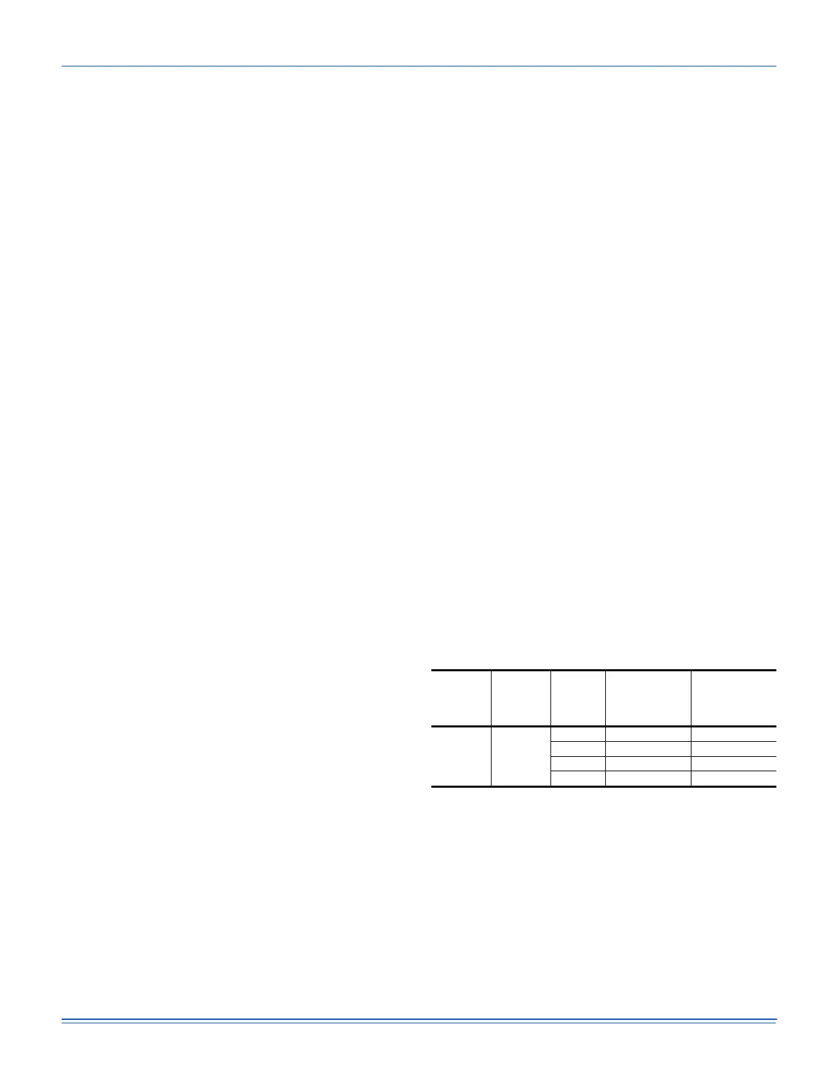
Table 26: Limit Control Setting
Unit
(Tons)
Voltage
Heater
Kw
Temperature,
Limit Switch
1, 2
Opens,
°F
Temperature,
Limit Switch
3, 4, 5, 6
Opens,
°F
15 and 20 415
18 120 170
36 120 170
54 120 170
72 120 170
 Loading...