1061903-XIM-A-0713
32 Johnson Controls Unitary Products
Air Balance
Start the supply air blower motor. Adjust the resistances in both
the supply and the return air duct systems to balance the air
distribution throughout the conditioned space. The job
specifications may require that this balancing be done by
someone other than the equipment installer.
To check the supply air CFM after the initial balancing has been
completed:
1. Remove the two 5/16” dot plugs from the blower motor and
the filter access panels shown in the Unit Dimensions and
Rear View Clearances Figure 7.
2. Insert at least 8" of 1/4 inch tubing into each of these holes
for sufficient penetration into the air flow on both sides of
the indoor coil.
NOTE: The tubes must be inserted and held in a position
perpendicular to the air flow so that velocity pressure
will not affect the static pressure readings.
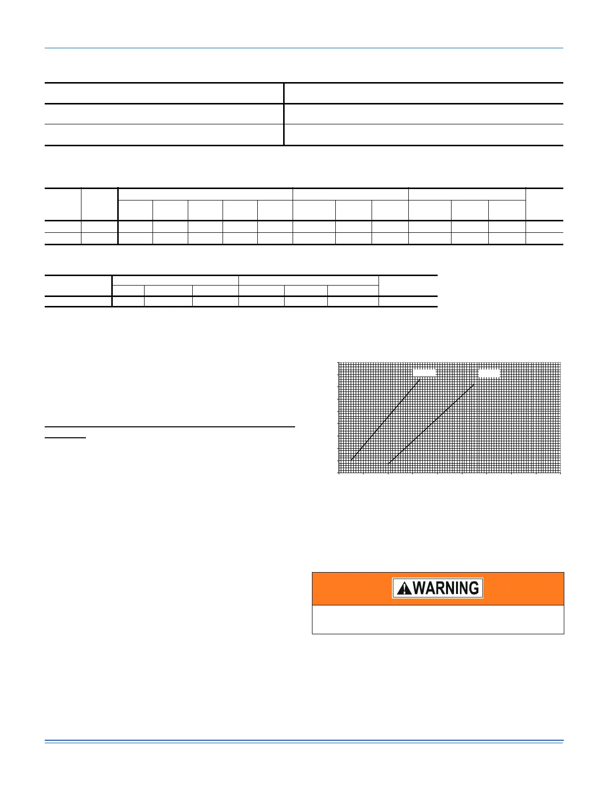
3. Using an inclined manometer, determine the pressure drop
across a dry evaporator coil. Since the moisture on an
evaporator coil may vary greatly, measuring the pressure
drop across a wet coil under field conditions would be
inaccurate. To assure a dry coil, the compressors should
be deactivated while the test is being run.
Figure 24: Pressure Drop Across A Dry Indoor Coil Vs.
Supply Air CFM For All Unit Tonnages
4. Knowing the pressure drop across a dry coil, the actual
CFM through the unit can be determined from the curve in
Pressure Drop vs. Supply Air CFM Figure 24.
After readings have been obtained, remove the tubes and
reinstall the two 5/16” dot plugs that were removed in Step 1.
NOTE: De-energize the compressors before taking any test
measurements to assure a dry indoor coil.
Table 21: RPM Selection
Size
(Tons)
Model HP Max BHP
Motor
Sheave
Blower
Sheave
6 Turns
Open
5 Turns
Open
4 Turns
Open
3 Turns
Open
2 Turns
Open
1 Turn
Open
Fully
Closed
18 0
(15)
ZF 4.1 4.72 1VP62 BK75 925 967 1009 1051 1093 1135 N/A
24 0
(20)
ZF 6.2 7.13 1VP75 BK100 895 926 956 987 1018 1049 N/A
* Maximum blower speed is 1400 RPM for ZF180 and 1200 RPM for ZF240
Table 22: Indoor Blower Specifications
Size
(Tons)
Model
Motor Motor Sheave Blower Sheave
Belt
HP RPM Eff. SF Frame
Datum Dia.
(in.)
Bore (in.) Model
Datum Dia.
(in.)
Bore (in.) Model
180 (15) ZF 4.1 1450 0.89 1.15 184T 4.4 - 5.4 1 1/8 1VP62 6.9 1 BK75 BX68
240 (20) ZF 6.2 1450 0.91 1.15 213T 5.8 - 6.8 1 3/8 1VP75 9.4 1 3/16 BK100 BX81
Table 23: Power Exhaust Specifications
Voltage
Motor Motor
CFM @
0.1 ESP
HP RPM
1
1. Motors are multi-tapped and factory wired for high speed.
QTY LRA FLA MCA
460-1-60 3/4 1075 1 4.1 2.2 2.75 5250
Failure to properly adjust the total system air quantity
can result in extensive blower damage.
PRESSURE DROP ACROSS A DRY INDOOR COIL VS
SUPPLY AIR CFM FOR ALL UNIT TONNAGES
0.25
0.3
0.35
0.4
0.45
0.5
0.55
0.6
0.65
0.7
45678910111213
NOMINAL CFM (THOUSANDS) SUPPLY AIR
PRESSURE DROP (IWG)
180MBH 240MBH
 Loading...