1061903-XIM-A-0713
Johnson Controls Unitary Products 33
Supply Air Drive Adjustment
The RPM of the supply air blower will depend on the required
CFM, the unit accessories or options and the static resistances
of both the supply and the return air duct systems. With this
information, the RPM for the supply air blower and the motor
pulley adjustment (turns open) can be determined from the
Blower Performance Data Tables.
Note the following:
1. The supply air CFM must be within the limitations shown in
the Blower Performance Tables 19 and 20.
2. Pulleys can be adjusted in half turn increments.
3. The tension on the belt should be adjusted as shown in the
Bet Adjustment, Figure 21.
4. Tighten blower pulley and motor sheave set screws after
any adjustments. Re-check set screws after 10-12 hours
run time recommended.
Belt drive blower systems MUST be adjusted to the
specific static and CFM requirements for the application.
The belt drive blowers are NOT set at the factory for any
specific static or CFM. Adjustments of the blower speed
and belt tension are REQUIRED. Tighten blower pulley
and motor sheave set screws after these adjustments.
Re-checking set screws after 10-12 hours run time is
recommended.
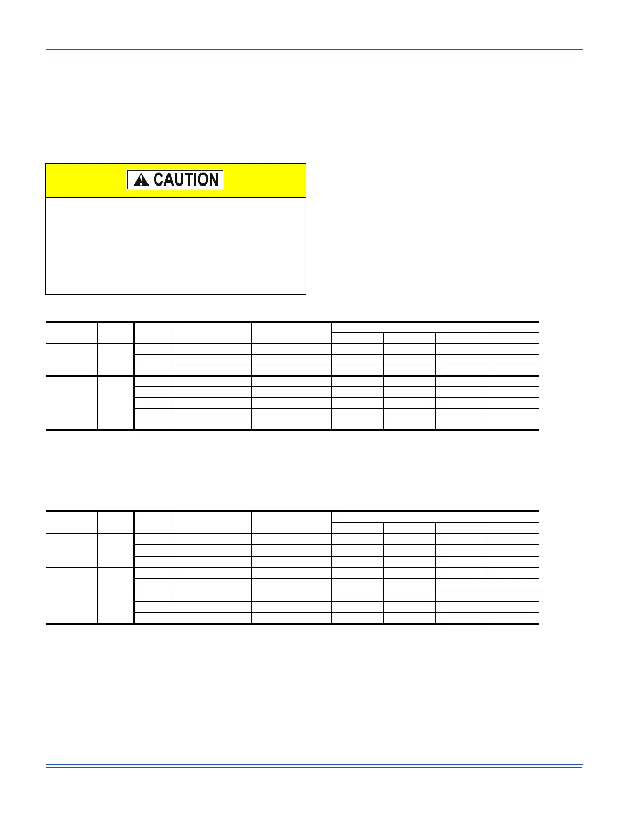
Table 24: Additional Static Resistance Imperial
Size
(Tons)
Model CFM Cooling Only
1
1. Add these values to the available static resistance in the respective Blower Performance Tables.
Economizer
2
3
2. Deduct these values from the available external static pressure shown in the respective Blower Performance Tables.
3. The pressure drop through the economizer is greater for 100% outdoor air than for 100% return air. If the resistance of the
return air duct is less than 0.25 IWG, the unit will deliver less CFM during full economizer operation.
Electric Heat kW
2
18 36 54 72
180
(15)
ZF
4500 0.10 0.10 0.10 0.10 0.20 0.20
6000 0.10 0.10 0.10 0.20 0.30 0.40
7500 0.10 0.10 0.10 0.30 0.40 0.60
240
(20)
ZF
6000 0.10 0.10 0.10 0.10 0.20 0.20
7500 0.10 0.10 0.10 0.20 0.30 0.40
9000 0.15 0.15 0.10 0.30 0.40 0.60
10500 0.15 0.15 0.20 0.40 0.60 0.80
12000 0.20 0.20 0.30 0.50 0.70 0.90
Table 25: Additional Static Resistance Metric
Size
(Tons)
Model M
3
/S Cooling Only
1
Economizer
2
,
3
Electric Heat kW2
18 36 54 72
180
(15)
ZF
2.12 25 25 25 25 50 50
2.83 25 25 25 50 75 100
3.54 25 25 25 74 99 150
240
(20)
ZF
2.83 25 25 25 25 50 50
3.54 25 25 25 50 74 100
4.25 37 37 25 74 99 150
4.96 37 37 50 99 150 199
5.66 50 50 74 124 174 224
1. Add these values to the available static resistance in the respective Blower Performance Tables.
2. Deduct these values from the available external static pressure shown in the respective Blower Performance Tables.
3. The pressure drop through the economizer is greater for 100% outdoor air than for 100% return air. If the resistance of the
return air duct is less than 62 Pa , the unit will deliver less M
3
S during full economizer operation.
 Loading...