RFSoC Data Converter Evaluation Tool User Guide 14
UG1287 (v2018.2) October 1, 2018 www.xilinx.com
Chapter 3
Hardware Design
Hardware Overview
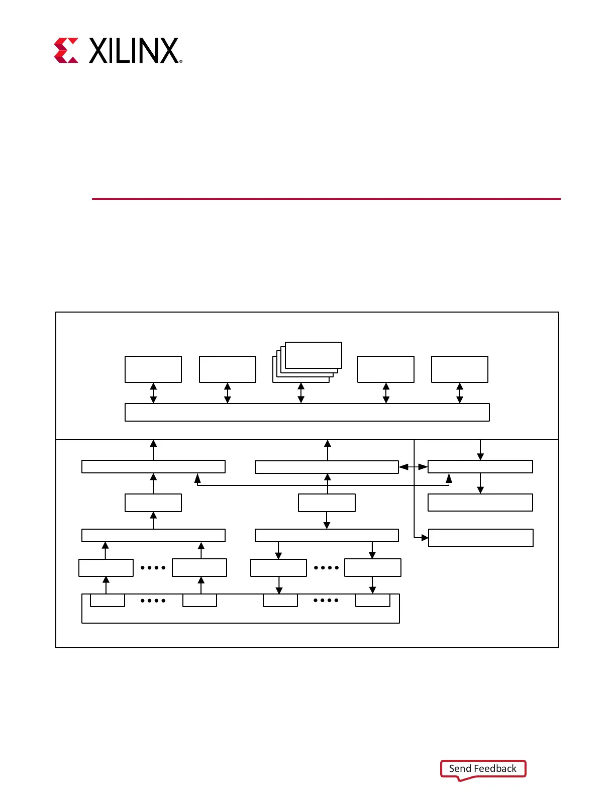
The Vivado IP integrator flow is used to create the hardware design which is partitioned
between the processing system (PS), RF Data Converter (RFDC), and programmable logic
(PL). Figure 3-1 shows the hardware block diagram.
X-Ref Target - Figure 3-1
Figure 3-1: Hardware Block Diagram
S_AXI_HP0_FPD
S_AXI_HP1_FPD
M_AXI_HPM0_FPD
Programmable Logic
Stream Pipe
ADC0
Channel Select Mux
ADC7
DMA
Stream Pipe
Stream Mux
DMA
DAC0
DAC7
RFdc
AXI Interconnect
AXI Interconnect
DDR4 Controller (MIG)
AXI Smartconnect
AXI Interconnect
DDR
Controller
GEM SD I2C
APU
APU
APU
APU
Processing System
Clocking and Control
GPIOs
Stream Pipe Stream Pipe
X21233-092118

 Loading...