RFSoC Data Converter Evaluation Tool User Guide 38
UG1287 (v2018.2) October 1, 2018 www.xilinx.com
Chapter 5: Evaluation Tool System Configuration using the GUI
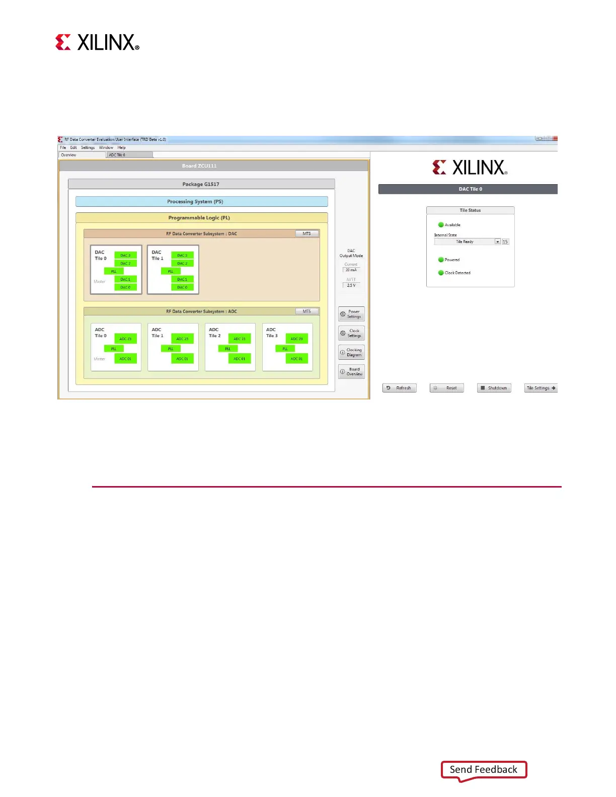
When selecting a tile, the tile status is displayed on the left side as shown in Figure 5-2,
including the power up state machine’s current state. Controls for reset and
shutdown/startup are provided. A reset reconfigures the tile to its original bitstream state.
Each individual tile configuration can be accessed by double-clicking the desired tile.
ADC Configuration
The ADC tiles contain the ADCs and supporting signal processing blocks or digital down
converters (DDCs). There are also clock generators or PLLs in each ADC tile. The GUI
supports the configuration of all these blocks.
The ADC settings need to be optimized for certain modes of operation. The modes relate to
where the signal being sampled by the ADC (Fin) lies in relation to the sampling frequency
(Fs) of the ADCs. As shown in Figure 5-3, the ADC configuration is similar to the RF Data
X-Ref Target - Figure 5-2
Figure 5-2: Overview of Tile Status

 Loading...