• the character ^ in front of an input/output signal name indicates that the
signal name may be customized using the PCM600 software.
• the character * after an input signal name indicates that the signal must
be connected to another function block in the application configuration
to achieve a valid application configuration.
• Logic diagrams describe the signal logic inside the function block and are
bordered by dashed lines.
• Signals in frames with a shaded area on their right hand side represent
setting parameter signals that are only settable via the PST, ECT or
LHMI.
• If an internal signal path cannot be drawn with a continuous line, the
suffix -int is added to the signal name to indicate where the signal starts
and continues.
• Signal paths that extend beyond the logic diagram and continue in
another diagram have the suffix ”-cont.”
Illustrations are used as an example and might show other products
than the one the manual describes. The example that is illustrated is
still valid.
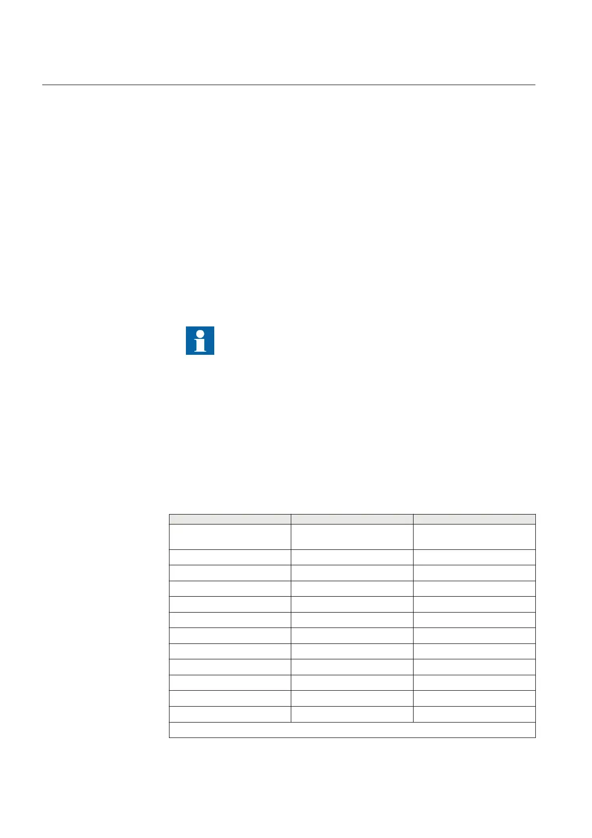
1.5 IEC 61850 edition 1 / edition 2 mapping
GUID-C5133366-7260-4C47-A975-7DBAB3A33A96 v4
Function block names are used in ACT and PST to identify functions. Respective
function block names of Edition 1 logical nodes and Edition 2 logical nodes are
shown in the table below.
Table 1: IEC 61850 edition 1 / edition 2 mapping
Function block name
Edition 1 logical nodes Edition 2 logical nodes
AGSAL AGSAL
SECLLN0
AGSAL
ALMCALH ALMCALH ALMCALH
ALTIM - ALTIM
ALTMS - ALTMS
ALTRK - ALTRK
BRCPTOC BRCPTOC BRCPTOC
BTIGAPC B16IFCVI BTIGAPC
CCPDSC CCRPLD CCPDSC
CCRBRF CCRBRF CCRBRF
CCSSPVC CCSRDIF CCSSPVC
CMMXU CMMXU CMMXU
CMSQI CMSQI CMSQI
Table continues on next page
Section 1 1MRK 511 423-UEN A
Introduction
18 Bay control REC650 2.2 IEC
Application manual
 Loading...

