8 ACH580 E-Clipse bypass and packaged drive user manual
Installation
• Use wire ties to permanently affix control/communications wiring to the hooked
wire race tie points provided maintaining a minimum 6 mm (1/4 in.) spacing from
power wiring.
• Use a separate motor conduit run for each motor.
Wiring overview
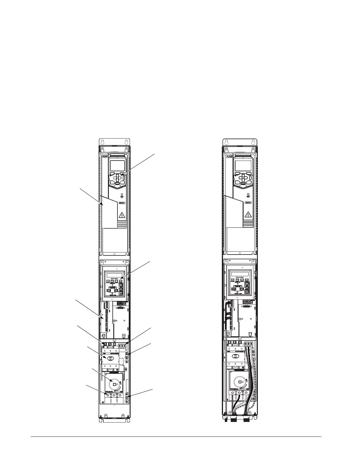
Connection and wiring diagrams – Vertical E-Clipse Bypass
ACH580 Vertical E-Clipse Bypass units are configured for wiring access from the
bottom only. The following figures show the layout and wiring connection points. For
drive control wiring, see page 52. Maintain appropriate separation of control and
power wires.
Drive Control Panel
E-Clipse Bypass
Control Panel
Disconnect Switch
or Circuit Breaker
Motor
Input
Motor Ground
Lug
Terminals
Terminals
Input
Ground Lug
Service Switch
(Optional)
V1/V2
ACH580 Drive
E-Clipse Bypass
Control Board
Terminals (X2)
Fuses
(Vx1-1, Vx1-2)
 Loading...