Counters
115
1SVC 440 795 M0100
Function of the counter function relay
:
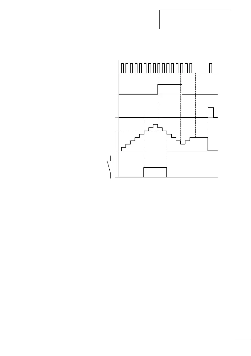
Figure 53: Signal diagram
1: Count pulses at the count coil CC…
2: Count direction, direction coil DC…
3: Reset signal at the reset coil RC…
4: Counter setpoint (the setpoint in the figure = 6)
5: actual value of the counter
6: contact of the counter, C
• Range A: The relay contact of counter
C with setpoint value 6
switches when the actual value is 6.
• Range B: If the counting direction is reversed, the contact is reset
when the actual value is 5.
• Range C: Without count pulses the current actual value is
retained.
• Range D: The reset coil resets the counter to 0.
Example: Counters, counting unit quantities, manual
counter value reset
The input I6 contains the necessary counter information and
controls the count coil CC1 of counter 1. Q4 is activated if
the setpoint is reached. Q4 remains switched on until I7
resets counter C1 to zero with the RC1 coil.
on
on
1
2
on
3
on
6
BACD
4
0
1
2
3
4
5
6
7
8
5
 Loading...


