Function relays
93
1SVC 440 795 M0100
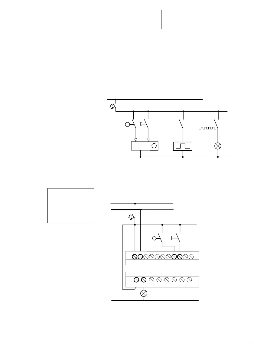
Example function relay with timer and counter relay
A warning light flashes when the counter reaches 10. The
example shows function relays C1 and T1. The S1
pushbutton actuator is used for the count signal. The S2
pushbutton actuator resets counter P1.
Figure 45: Hardwiring with relays
The wiring of the logic relay is as follows.
Figure 46: CL wiring and circuit diagram
The counter P1 is called C1 in the logic relay.
The timing relay K1T is called T1 in the logic relay.
L01–
P1
P1
K1T
K1T
C
R
H1
S1
S2
L01+
2s
Counter
Value 10
I5-------CC1
I6-------RC1
C1-------TT1
T1-------ÄQ1
12
H1
L01–
S2
L01+
L01–
+24 V
0 V I5 I6
S1
Q 1
 Loading...


