CL operation
75
1SVC 440 795 M0100
The options for setting output and marker relays are listed
with the description of each coil function.
The coil functions and parameters are listed with the
description of each function relay.
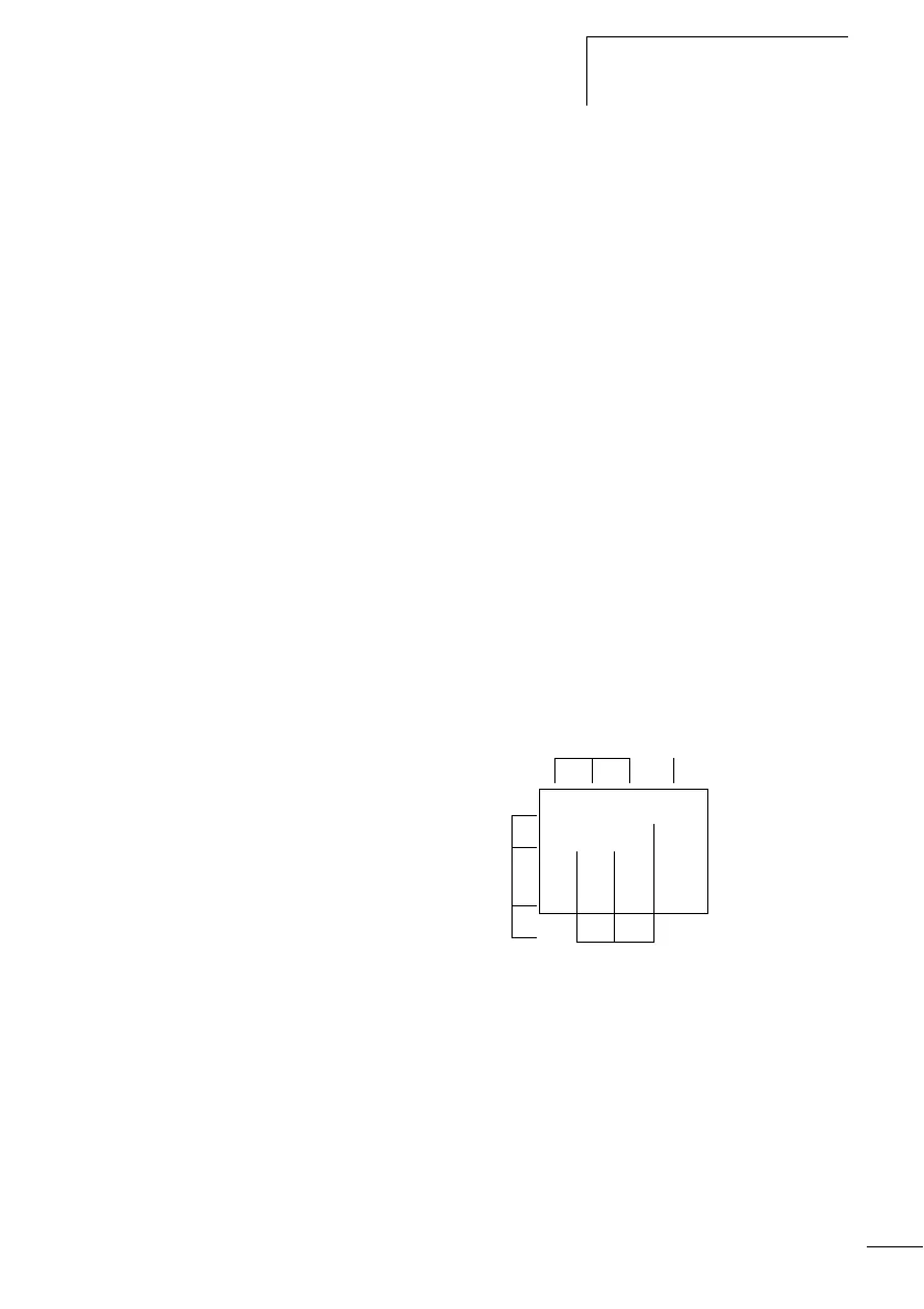
Circuit diagram display
In the logic relay circuit diagram, contacts and coils are
connected up from left to right – from the contact to the coil.
The circuit diagram is created on a hidden wiring grid
containing contact fields, coil fields and rungs. It is then
wired up with connections.
• You can add switching contacts in the three contact
fields. The first contact field is automatically connected to
the voltage.
• You add the relay coil to be controlled together with its
function and designation in the coil field.
• Every line in the circuit diagram forms a circuit
connection or rung. Up to 128 rungs can be wired in a
circuit diagram.
• Connections are used to produce the electrical contact
between switching contacts and the coils. They can be
created across several rungs. Each point of intersection is
a connection.
Contact fields Coil field
Rungs/
Current paths
I1-I2uT1-ÄQ1
Q1-Ö1kêê êêê
êê êê êê êêê
êê êê êê êêê
Connecting lines
 Loading...


